
Non-volatility and dual illumination in a Micro-LED pixel, from a floating gate
Display and illumination may no longer need to be built as separate modules. A Hunan University group stacked a single transparent floating gate memory on each pixel to make a Micro-LED that holds an image without refresh and doubles as lighting. Static power in the off state is 1.4 picowatts per pixel. A result worth watching for any planning team thinking about a new product category.
DOI 10.1038/s41467-026-76263-3Micro-LED displays have always been built with screen and lighting made separately, because the circuits differ and the drive schemes differ. A Hunan University group merged the two into one chip merely by stacking a single transparent memory device on each pixel. The image does not go out without continuous power. In the off state one pixel uses 1.4 picowatts, less than most leakage currents.
1. Why this was a hard problem
Until now a Micro-LED display had to be supplied with power without interruption to keep the screen on, because there was no non-volatile function storing the display state. Attempts to hold a static image for a long time, or to make a reconfigurable screen in a power-limited environment, ran into this limit every time.
Worse, the circuit itself was designed as “display only.” Adding a lighting function that spreads light uniformly over a large area meant bolting on a separate module, increasing volume, power and control complexity together. With screen and lighting made from different circuits, there was no ready way to merge them.
2. The turn: one switch per pixel
The group stacked a transparent ITO floating gate memory (FGM) vertically on top of the Micro-LED. One emitter and one memory per pixel (1M1D). Depending on which voltage is applied to the combination, the same chip wears two faces.
- One transparent floating gate memory per pixel, stacked vertically with the Micro-LED (the 1M1D structure)
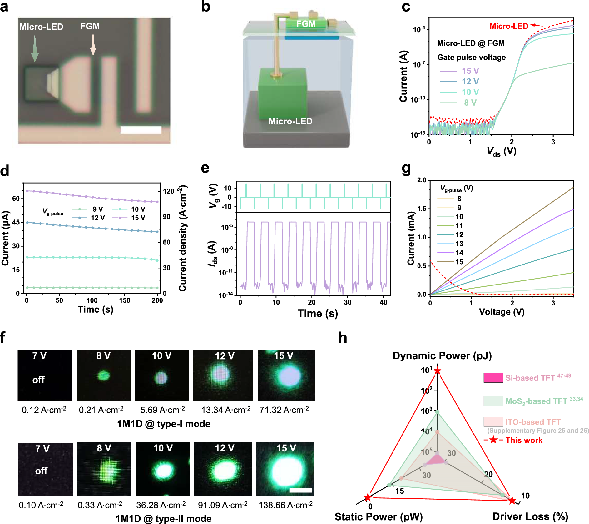
- Apply a gate voltage per pixel (Type-II) and that pixel’s state is stored, so the image is held without refresh
- Apply a common anode voltage across the whole array (Type-I) and it turns into uniform lighting with no storage function
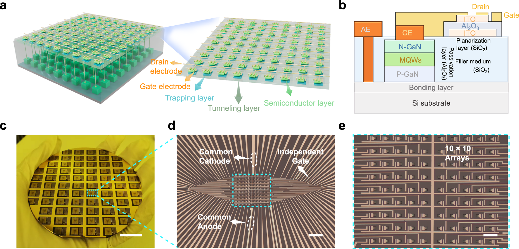
The group named this structure INDIS (Integrated Nonvolatile Display–Illumination System).
3. Result: standby power close to zero
In statistics over 100 devices on a 4-inch wafer, the Type-II (three-terminal, display mode) on/off ratio averaged 1.75×10⁸ and fabrication yield exceeded 98%. The switching energy to flip one gate pulse is 11.41pJ. A 10×10 pixel array (pitch 45µm, Micro-LED size 7.5µm, equivalent to about 564 PPI) was used to display the characters “I ♥ HNU” in practice, and the supplementary material carries a demonstration of the characters “MICRO” scaled up to 200×128 pixels.
Table 1 · Standby power comparison (based on Table S2 of the same paper; only figures consistent with the body text are used)
| Approach | Static (off) power | Driver voltage loss |
|---|---|---|
| This work (ITO floating gate) | 1.4 pW | 11.71% |
| ITO-TFT | 20 pW | 11.43% |
| MoS₂-TFT | 14 pW | 14.3% |
| LTPS-TFT | 33 pW | 29.6% |
Static power means the current one pixel keeps leaking in the standby state. Source: paper Table S2.
4. What it means: the line between screen and lighting blurs
The practice of building display and lighting separately always had volume and power budget as its problem. This work erases that line with one circuit and one difference in how voltage is applied. It looks especially useful for static screens that have to stay on (standby information display, low-power wearable interfaces) and for small devices that need both screen and lighting.
This demonstration is limited to blue and green Micro-LEDs, though. A result integrating the red needed for full colour is not in this paper.
5. At a glance
| In one line | stacking a transparent floating gate memory on a Micro-LED to switch display and illumination on one chip (static power 1.4pW) |
| Core results | on/off ratio >10⁸ · 96.87% brightness retention at 200 seconds · a 564 PPI-class 10×10 array demonstration |
| Strengths | holds the image without refresh, standby power far below competing technologies (LTPS-TFT and others) |
| Published | Nature Communications, 2026 (Article in Press) |
6. Key terms
- floating gate memory
- A non-volatile memory structure storing information in an insulated gate that traps charge. The state is held even with the power off.
- 1M1D
- A structure pairing one memory and one diode per pixel. It allows per-pixel control without complex compensation circuitry.
- non-volatile display
- A display whose screen content is held even when the power supply stops or it is not refreshed.
- INDIS
- Integrated Nonvolatile Display–Illumination System. The name this paper gives its device concept combining display and illumination on one chip.
The other 14 papers of the week are swept briefly in the display paper briefing for week 1 of August.