Can Face ID get rid of the hole in the screen too?
While the fingerprint, ambient light and proximity sensors went under the screen one after another, Face ID alone has stayed on top of it for 9 years. The diffraction that creates 30,000 dots is the same principle that, on meeting the panel, copies those dots and breaks them. The answer the industry produced was not to add more dots but to cut them by more than ten times. For optical and sensor design engineers who have to put 3D sensing under a panel, from operating principle through to three branches of solution.
This article was published before the English edition began, so the labels inside its figures and simulators are in Korean. The caption and the note under each figure are in English.
1. There is a rule in the order things went under the screen
The iPhone 18 Pro is unveiled next month. Several accounts point at one thing. The Face ID module goes under the screen and the Dynamic Island shrinks or disappears. The panel is supplied as LTPO+ OLED from Samsung Display and LG Display, and the feature named for this panel is “a structure that allows an infrared camera to be placed under the display.”
Putting a sensor under the screen is not new. If anything, Face ID is the latest.
The first to go under was the optical fingerprint sensor. Synaptics announced Clear ID in 2017-12, and in early 2018 the Vivo X20 Plus UD became the first commercial product carrying it. This sensor has no separate light source. It uses the OLED screen itself as the illuminator. It lights the pixels where the finger touches to illuminate the fingerprint, and an image sensor under the panel reads the returning light. That is also why it works only on OLED. The light has to pass through the panel. After that the ambient light sensor and the proximity sensor went under, and the camera is on its way.
For Apple alone the proximity sensor is homework already done. The title of the paper Apple engineers presented as an invited talk at the SID conference in 2023 was “Through OLED-Display Proximity Sensing,” and the abstract states that it discusses the solution implemented in the iPhone 14 Pro and 14 Pro Max.1
This order is not chance. The further away what a sensor has to look at, the later it went under. The fingerprint sensor looks at a finger touching glass. The ambient light and proximity sensors look a few millimeters to a few centimeters ahead. The camera looks at infinity. And Face ID looks at a face 25 to 50cm ahead, in three dimensions at that.
What changes as distance grows? In Section 5 we will show that this order resolves into a single physical quantity, but first we have to pin down why Face ID alone has stayed on top of the screen for 9 years. What is different between hiding one camera and hiding a 3D sensor?
The answer is diffraction. But not diffraction in the way this series has treated it so far. In Face ID, diffraction is not first an obstacle to overcome but the driving force that makes the technology work. The 30,000 dots are made by diffraction. And that very principle, on meeting the panel, brings the technology down.
Let us set out how Face ID works first. Three stages.
2. Face ID works in three stages
2-1. Stage 1: is there a face, and is it looking at me
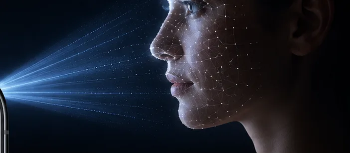
Lift the device or tap the screen and the TrueDepth camera turns on. The element that works first here is not the dot projector but the flood illuminator. As the name says, it is a light that “floods” near-infrared broadly and evenly. Under this uniform illumination the infrared camera takes one ordinary 2D infrared image.
This stage has two jobs. Is there a face in front of the screen? And is that face looking at the device now? Apple’s platform security document sets out this order. “Once it confirms the presence of an attentive face, Face ID then detects whether the user’s eyes are open and the user is gazing at the device to confirm that the user is looking at the camera and intends to unlock it.”2
Because of this check, called attention aware, holding a phone in front of a sleeping person’s face does not unlock it. It is a security design, not a convenience feature.
What Stage 1 requires is light spread evenly over a wide angle, and 2D image quality good enough to tell eyelids and gaze apart. Up to here it is effectively the same kind of problem as the UDC camera. If it blurs, restoration can be attempted on the blur as it is.
2-2. Stage 2: depth is made from 30,000 dots
Once gaze is confirmed the dot projector turns on. From here on is the body of Face ID.
The structure of the dot projector was set out for comparison in a paper published in Nano Letters in 2025. Inside a module of 61.25 mm³ there are about 366 VCSEL emitters, followed by 4F optics, a doublet lens, a folding waveguide, and a diffractive optical element (DOE). The 366 emitters are copied as they pass the DOE and become more than 32,000 dots.3
One thing needs noting about the number. Apple’s current official document says only “thousands of infrared dots.” The figure of 30,000 has been widely cited since the iPhone X announcement in 2017, and the paper above wrote more than 32,000. This article follows the paper’s value while noting that Apple has not itself stated a definite number.
When these dots are thrown onto a face, the infrared camera reads the pattern back. The principle is structured-light triangulation. Projector and camera are separated by a fixed distance (the baseline). If the face were a flat board, the dots would land exactly where predicted. But where something protrudes, like a nose, the dot shifts sideways from its predicted place. The amount of shift is the depth at that point.
The relation between shift and depth is simple. With baseline b, distance to the face z, and protrusion Δz, the disparity (sideways shift) is roughly b·Δz/z.
What matters is that this shift is not all-or-nothing. A face does not divide neatly into plane and protrusion. Height varies continuously, so each dot shifts by a different amount. Below, a simple sphere stands in for a face to show how continuous change in surface height bends the dot pattern.
The highest point at the center shifts most, and the shift dies to 0 toward the edges. This distribution of shift is itself the solid shape. The camera does not measure depth directly. It reads only how far a dot moved and computes depth back from that.
One distinction has to be made here. The amount of shift and the spacing between dots say different things. The shift is proportional to the height at that point. The spacing between two neighboring dots, by contrast, is proportional not to height but to the gradient of height. The top of the sphere shifts most but is close in height to its surroundings, so spacing barely changes. Conversely the rim of the sphere hardly shifts at all, yet it is where the surface bends steeply, so spacing changes most. You can see this in the strip below the simulation above. Dots spread apart on the left of the sphere and close up on the right. At the default the spacing widens by nearly half and narrows by around 40%.
That dots bunch up where the gradient is steep has a practical meaning. On the bridge of the nose or the jawline, where the surface turns sharply, dot density locally collapses and depth there is measured sparsely by that much. That the part of a face with the greatest individual variation is exactly the steepest part is a structural limit of this method.
The disparity produced by a 25mm protrusion at 30cm is about 2mm. And when 32,000 dots are thrown around a face, the spacing between dots is about 1.5mm. That is, the signal a nose-height protrusion produces is worth one or two dot spacings. Reading that fine displacement 30,000 times to reconstruct the surface of a face is Stage 2.
Apple states that Face ID works best at 25 to 50cm from the face.4 Push the distance to 500mm in the simulation above and you can see the disparity fall to less than half. That is why there is an upper bound on working distance.
What Stage 2 requires is not the amount of light but the geometric accuracy of the dots. Where a dot lands is the information. This distinction is the core of the whole article.
2-3. Stage 3: converted into a mathematical representation and compared
Once the depth map and the 2D infrared image are made, this data is digitally signed and sent to the Secure Enclave. The Secure Neural Engine inside converts the data into a mathematical representation and compares it with the representation stored at enrollment. The enrollment data too is itself a mathematical representation of the face captured from several angles.2
Apple has disclosed two security measures at this stage, and both bear directly on the argument of this article.
First, randomization of capture order. The order in which the 2D image and the depth map are taken is randomly changed each time. This is to defeat attacks replaying recorded signals.
Second, a device-specific random pattern. In Apple’s own words, it “projects a device-specific random pattern.”2 It means the dot pattern is not an identical grid on every iPhone but a random arrangement differing by device.
Why does this randomness matter? As covered later, erasing in software the false dots the panel creates requires knowing “what the real pattern is.” Yet the design philosophy of Face ID is on the side of making that pattern unpredictable.
The probability of false acceptance is “less than 1 in 1,000,000 that a random person could unlock it,” and 5 consecutive failures require a passcode.4 That a threshold at this level is in place comes back later when answering the question “would it not be fine if performance dropped a little?”
2-4. The three stages break down differently under the screen
| Stage | What it does | What it requires | Under the screen |
|---|---|---|---|
| Stage 1 | face and gaze detection | uniform illumination, 2D image quality | blurs (restoration can be attempted) |
| Stage 2 | 30,000 dots → depth map | geometric position of the dots | false dots appear (not a subject for restoration) |
| Stage 3 | mathematical representation matching | statistical consistency of the input | errors from stages 1 and 2 accumulate as they are |
The problem is overwhelmingly concentrated in Stage 2.
3. Diffraction is both the driving force and the destroyer of this technology
3-1. Turning 366 into 30,000 is also diffraction
It might seem that the dot projector has 30,000 VCSELs embedded, but it does not. There are only 366 emitters. The rest are made by the diffractive optical element. A DOE splits light into many directions with a regular microstructure, so one emitter is copied into a grid and becomes dozens of dots. Multiply 366 by the copy factor and you get 30,000.
Competing products using meta-optics work on the same principle. Metalenz’s Starlight projector collimates and diffracts 391 VCSEL emitters through a metasurface to make about 18,000 dots.
That is, structured-light 3D sensing is a technology that holds together by controlling diffraction precisely. Hold on to that fact going into the next step.
3-2. The panel is a grating too
The fine wiring and electrode arrays of an OLED panel repeat regularly. What happens when light at the wavelength scale passes through a regularly repeating structure is already settled. It acts as a diffraction grating.
A patent document states this explicitly. It is the wording in the original of trinamiX’s “Depth measurement through display” patent.
“The microstructure of a transparent or translucent display acts like a diffraction grating structure for laser light.”5
The result is this. One real dot made by the DOE is copied once more as it passes the panel. Zero-order diffraction (the brightest, real dot) stays in the original place, and ±1st and ±2nd order ghost dots appear around it. The camera receives them all with no way to tell real dots from ghosts.
3-3. How far away does a ghost dot land
Let us quantify it. The grating equation is sinθ = mλ/d. With wavelength λ = 940nm and the panel’s repeat period d taken as 55µm, the first-order diffraction angle θ₁ is about 0.98°. A small angle, under 1 degree.
But the face is 30cm away. Over 30cm, that 0.98° becomes a displacement of about 5.1mm.
Put this number next to the two from the previous section.
| Value | Size |
|---|---|
| Spacing between dots | about 1.5mm |
| Real disparity from a 25mm nose | about 2.1mm |
| Ghost dot displacement from panel diffraction | about 5.1mm |
The false displacement the ghost dot creates is more than twice the real signal an entire nose creates. And it is more than 3 times the dot spacing. That is, the ghost dot does not sit obediently at its own place; it jumps about three slots over and lands exactly where another real dot ought to be.
Below you can move the dot count and panel grating pitch yourself. Dots marked in orange are those that “became indistinguishable from a ghost.”
At the default (32,000 dots, 55µm) the correspondence failure rate comes out in the 80% range. It means most of the face surface cannot be trusted.
3-4. A blurred photo and a false dot are different problems
Here the decisive difference from the UDC camera appears.
In a camera, diffraction makes the image blurred. Blur is a deterministic transform described by a point spread function (PSF), and knowing the transform you can attempt the inverse. That is why neural restoration holds.
In structured light, diffraction does not stop at blurring the image. It creates dots that were not there. And what a structured-light algorithm does is match “which dot the projector threw is this dot the camera saw” (the correspondence problem). Pick one false dot as real here and the depth at that point is not blurred but fixed at a completely different value.
Blur is a subject for restoration. A wrongly fixed depth is not. There is no original to restore in the first place.
4. So how far does performance drop
To the objection “restoration algorithms have got better, surely it works out somehow,” measured data can answer. Though the data is for 2D camera face recognition, not structured light. It should be read bearing in mind that this is a far easier condition than structured light.
A paper published in the Journal of the SID in 2025 quantified it. The first author is at Samsung Display and the work was carried out with Seoul National University. It measured pair matching accuracy, judging whether two face images are the same person, under under-screen degradation.6
| Condition | Pair matching accuracy |
|---|---|
| Original image | 88.3% |
| Under-screen degradation (measurement-based UDC-SIT) | 48.7% |
| After neural restoration (ECFNet) | 78.9% |
The moment it goes under the screen, accuracy falls to coin-flip level. Restoration brings it back to 78.9%, but not to the original 88.3%. About 9.4 percentage points are permanently gone.
Put that gap next to the false acceptance threshold of 1 in 1,000,000 and the problem is clear. Unlocking is not a convenience feature but payment authentication. It is not an area where a drop of a few percentage points can be waved off as “good enough.”
And 2D will not do to begin with. Researchers from Infineon and Graz University of Technology nail it in the first sentence of their paper on under-display ToF. “Secure face authentication requires additional information in the form of the third dimension.”7 2D face recognition is defeated by a printed photograph. Depth information is what makes a defense. That is why under-screen 3D sensing is homework that cannot be avoided.
5. What decided the order was the Fresnel number
Here it is worth stepping back and looking at this whole series again. The sensors covered so far seemed to suffer different problems. The fingerprint sensor mixes light from neighboring pixels, the ambient light sensor loses viewing angle, the proximity sensor struggles with background noise, and the camera blurs.
A paper by a Sun Yat-sen University group published in Optics Express in 2025 organized these into a single index. The Fresnel number.8
N = (a² / λ) × (1/z + 1/z′)
a is the size of the transmitting aperture on the panel, λ the wavelength, and z and z′ the distances to the source and the receiver. This one value determines how light propagates. At short distance the wavefront curves strongly and the Fresnel number is large, and light is simply blocked or passed. At long distance the Fresnel number converges to 0 and light spreads by diffraction.
The “order of going under” from Section 1 follows exactly this axis.
| Sensor | Target distance | Fresnel number | Propagation regime | Problem faced |
|---|---|---|---|---|
| Fingerprint | contact (~0) | very large | geometric optics (occlusion) | light mixing between pixels |
| Ambient light (UPS2) | a few cm and up | about 10 | geometric optics (shadowing) | reduced viewing angle |
| Proximity (UPS1) | a few mm to a few cm | about 1 | Fresnel diffraction | background noise |
| Camera (UPC) | infinity | 0 | Fraunhofer diffraction | blur and flare |
| Structured-light 3D (UPS3) | 25 to 50cm | close to 0 | diffraction + correspondence collapse | false depth |
Why the fingerprint sensor went under first appears here. The finger is touching the glass so the distance is effectively 0, and light passes or is blocked with no room to diffract. So the problem is not optical but geometric. In fact, according to work cited by that same paper, what governed the accuracy and angular response of an in-cell fingerprint sensor was not diffraction but occlusion by the black matrix and the pixel definition layer.9 The solution is geometric too. A collimator or microlens narrows the accepted angle and cuts off light leaking in from neighboring pixels.
At the other end sits Face ID. The distance is long so the Fresnel number is near 0 and light moves entirely in the diffraction regime. On top of that, unlike other sensors that read the intensity of light, structured light reads the position of light. It uses position as information in a place where diffraction shakes position.
Measured values in the same paper back up this picture. The viewing angle of the ambient light sensor narrowed from 120° to 92.5° at full width half maximum, and to 60.9° in a structure with the color filter placed on the encapsulation film. On the camera side, a pixel array at 100µm pitch with 30% aperture ratio dropped image similarity (SSIM) to 0.65.
There is one more value in this paper worth noting. The proximity sensor in the commercial smartphone the researchers took apart had a wavelength of 1330nm rather than 940nm. That number comes back later.
6. Three reasons you cannot push it through with brightness
If signal is short, why not just fire harder? This intuition is blocked in three places.
First, two passes through. It is exactly the structure covered in the UPS1 episode of this series. Light passes the panel once going out and once coming back after reflecting off the face, so the final signal is proportional to the square of transmittance (T²). Apple’s patent notes the same problem, stating that more than 80% of visible light can be lost passing through the display stack.10
Second, eye safety. The dot projector is an infrared laser. It is invisible to the eye but it is a laser, so it must stay within the output limits of international safety standards. Apple itself notes this constraint in its documents. It gives “low output” as a reason the TrueDepth system is safe, and warns that if the device is damaged the laser system may be disabled for safety reasons.4 Output is not a variable a designer can raise freely.
Third, TFT photodegradation. Fire IR harder and this time the panel itself is hurt. LTPS and oxide TFTs respond to light, so strong infrared entering from the back produces photocurrent and shifts the threshold voltage. The watermark artifact covered in the UPS1 episode is this. A paper presented at the SID conference in 2024 dealt with exactly this subject, analyzing the effect of infrared irradiation on an OLED screen, particularly the TFT, and proposing optimization.11
There is one piece of good news. The polarizer is not the culprit here. A circular polarizer loses its polarizing function above 800nm in the near infrared and passes more than 90% straight through. A polarizer that eats nearly half of visible light is almost transparent to near infrared. It is the opposite of the UPS2 episode, where the trend of removing the polarizer actually made the ambient light sensor problem worse.
7. Three branches of solution the industry chose
So how is it being solved? Following the patents and conference papers, it splits three ways.
7-1. Open the panel: 34.4% at 940nm
The most direct approach. Strip the subpixels and wiring in the screen above the sensor to make a path for infrared.
Apple’s patent US12201004 describes this method in detail. Filed in 2020-04 and granted in 2025-01, its inventor list contains the very authors of the SID invited talk mentioned earlier. The methods the patent presents are these.
- In the region overlapping the sensor, subpixels are removed at 10 to 90%, with half as the base case
- The removal method is to “iteratively remove the nearest subpixel of the same color.” Neighboring pixels compensate for the missing color, so it is not easily noticed
- And decisively, the horizontal and vertical control lines are rearranged to create “a continuous open region that reduces the amount of diffraction as light passes the display”10
The last item is worth noting. Apple named diffraction directly in a patent document as the obstacle to under-panel sensing, and stated reducing it as a design goal.
A figure showing how far this approach actually goes is in a 2024 SID paper. On a 6.55-inch panel, two Face ID sensor regions of 4mm × 14mm were made, and applying a “TFT inside” method secured 34.4% transmittance at 940nm. And it held 400 PPI across the whole screen.12
How much 34.4% is can be seen by comparison. The infrared transmittance of an ordinary screen region cited in the UPS1 episode of this series was 3 to 10%. Design a dedicated transmitting window and it rises 3 to 10 times. Converted to a round trip, the received signal that was 0.09 to 1% becomes about 11.8%. Two orders of magnitude change.
What pushed under-screen Face ID into the realm of the possible was not a new algorithm but this transmittance.
7-2. Change the wavelength: abandon 940nm
The second approach goes around the problem. If the panel does not open at 940nm, move to a wavelength the panel passes better.
Patent US11146745 explicitly proposes this direction. It is a configuration placing infrared components behind a non-emissive region with no physical hole, while moving the wavelength to the 1100 to 1600nm band, optimally 1300 to 1400nm. This patent defines transmittance criteria of 30%, 50%, 70% and even more than 90%.
And this is not an idea on paper. The proximity sensor in the commercial smartphone the Optics Express paper took apart was already using 1330nm. It is measured evidence that the band the patent proposed is in an actual product.
There is a price. The sensitivity limit of a silicon photodiode is about 1100nm. The trinamiX patent also pins the silicon band at 700 to 1100nm. Going to the 1300nm range means changing the detector material itself, which means different cost and supply chain. It is a change one proximity sensor can bear, but whether the same choice can be made for an entire 3D sensing module is another matter.
7-3. Cut the dots: from 30,000 to 2,500
The third is the most counterintuitive, and therefore the most interesting.
The trinamiX patent states that for under-screen 3D sensing the projection pattern is limited to “fewer than 2,500 dots per field of view.” That is more than a tenfold cut from 32,000. There are two reasons.5
First, cutting dots raises the output per dot. What eye safety standards bind is total output. Pour the same total into ten times fewer dots and each dot becomes ten times brighter. Since the 0th order is the brightest of the diffraction orders, the brightness gap between real dots and ghosts widens.
Second, you can sort by brightness and filter. The patent’s wording: “brighter reflection features are prioritized in correspondence matching.” Zero-order diffraction is inherently brighter than higher orders, so line them up by brightness and the top is real. Beam profile analysis is added to exclude false features.
And when dots are sparse, the probability that a ghost lands on another real dot’s place is lower to begin with. Pull the dot count slider in the earlier simulation all the way toward 2,500 and you can see the correspondence failure rate fall from the 80% range into the 10% range.
The price is clear. Depth map resolution. Read a face surface with 2,500 points instead of 32,000 and the fine undulations of the face disappear. It is a trade selling resolution to buy reliability.
| Approach | What you get | What you give up |
|---|---|---|
| ① Open the panel | 34.4% transmittance | pixel density, process complexity |
| ② Change the wavelength | favorable panel transmission | cannot use silicon detectors |
| ③ Cut the dots | correspondence reliability | depth map resolution |
8. And yet it has already been commercialized
Read this far and under-screen face recognition looks like it is still at the research stage. It is not.
trinamiX, a BASF subsidiary, announced as early as 2022-02 that it had passed all biometric security tests while placed behind an OLED. Android biometric security Class 3 (Strong), FIDO Alliance Level C, and a 0% acceptance rate against thousands of spoofing attempts including silicone masks. The core technology is skin detection based on beam profile analysis, judging whether the object in front of the camera is actual human skin.
The steps after that continued. In 2024-02 it released a low-cost behind-OLED solution with Visionox and STMicroelectronics, and at Display Week in May the same year it demonstrated face authentication mounted behind a foldable screen. In 2025-01 it combined with NIL Technology’s meta-optics to shrink the module further.
The Chinese camp is not empty either. Visionox released its UDC solution InV see® in 2020 and then announced an under-display 3D face recognition full-screen solution in 2022. The company says it reached payment-grade verification level.
So why is Apple the latest? The earlier numbers answer that. A false acceptance threshold of 1 in 1,000,000, an architecture bound to the Secure Enclave and the Secure Neural Engine, and an ecosystem with payment and app authentication hanging off it. Passing certification and moving a system that has already worked at that level for 9 years under the screen without any performance drop are different problems.
9. What to check next month
When the iPhone 18 Pro is unveiled, the items below verify or refute the argument of this article. Checking in this order while watching the announcement will do.
① Does the hole disappear entirely, or only shrink? If it disappears entirely, both the dot projector and the infrared camera went under the panel. If it only shrinks, it is likely only one of the two went under. Worth remembering that the configuration the 2024 SID paper presented was two windows of 4mm × 14mm.
② Is the working distance of 25 to 50cm held? When signal margin is short, the first thing adjusted is operating range. If this figure narrows, it is a signal that there was no room in securing transmittance.
③ Is recognition with a mask still supported? Recognition with a mask judges from only the narrow region around the eyes, so it is more sensitive to depth map resolution. If the choice to cut the dot count was made, this function is affected first.
④ Does enrollment take longer? If the number of head turns at enrollment increases, it can be read as an indirect signal that the per-device calibration burden has grown.
⑤ Does Apple state the wavelength? Whether 940nm was kept or it moved to the 1300nm range is the fork dividing which of the three branches was chosen.
10. Remaining questions
Are a random pattern and ghost removal compatible?
The ghost dots the panel makes are deterministic in principle. The grating structure is fixed, so where ghosts appear can be calculated and subtracted by per-device calibration. Yet the security design of Face ID is on the side of leaving the projected pattern as a random arrangement differing by device, and randomizing the capture order as well. The requirement to increase predictability and the requirement to reduce it meet inside the same system. How the two were separated has not been disclosed.
How much resolution can be sold?
trinamiX’s 2,500 dots also means the minimum resolution required for authentication is around there. But authentication is not the only use of a 3D sensor. Animoji, portrait mode and AR applications use denser depth maps. Cut the dots for authentication and these functions come down with them. Whether authentication and capture are split into different modes becomes an actual design decision.
11. Key terms
- Structured light
- A method that projects light of a known pattern onto an object and reconstructs 3D shape from how the pattern appears displaced.
- Correspondence problem
- The problem of matching which dot the projector cast a dot observed by the camera is. It is the core computation of structured-light 3D sensing.
- DOE
- Diffractive optical element. A regular microstructure splits light into many directions, copying one source into many dots.
- Disparity
- The amount by which an object's position appears displaced when viewed from two points separated by a baseline. It is inversely proportional to depth.
- 0th and higher-order diffraction
- The orders into which light splits after a grating. The 0th order is the straight-through component and the brightest; ±1st and above make ghost dots.
- Fresnel number
- An index computed from aperture size, wavelength and distance that divides which regime light is in among geometric optics, Fresnel diffraction and Fraunhofer diffraction.
- Flood illuminator
- An illumination element that spreads uniform near-infrared over the whole face so that a 2D infrared image can be obtained.
Footnotes
-
SID Symposium Digest 54(1) 778–781 (2023), “54-1: Invited Paper: Through OLED-Display Proximity Sensing.” Among the authors, Chris Glazowski, Warren Rieutort-Louis and Abbas Jamshidi Roudbari are the same people as the inventors of Apple patent US12201004 below. ↩
-
Apple Platform Security, “Biometric security” (published 2024-12-19). The quotation follows the wording of Apple’s own document. ↩ ↩2 ↩3
-
Nano Letters 25(29), 11382–11390 (2025). The figures are Face ID module specifications the paper compiled for comparison with its own device, not values officially announced by Apple. ↩
-
Apple support document “About Face ID advanced technology” (published 2024-12-09). ↩ ↩2 ↩3
-
US11989896 and continuation US12406384 (trinamiX GmbH). The quotation is carried over from the patent original. ↩ ↩2
-
Journal of the SID 33(5), 698–705 (2025). The degraded images were made by a generative model trained on a measured UDC dataset, and the paper states the limitation that they are not actual captures. ↩
-
IEEE Sensors Journal 22(1), 264–278 (2022). A study on stray light suppression for under-display ToF, reporting suppression performance of the proposed method above 80%. ↩
-
Optics Express 33(15), 30847–30858 (2025). It experimentally verified three cases, ambient light sensor, camera and proximity sensor, on commercial smartphones. Structured-light 3D sensing was not included in the paper’s verification, and the last row of the table is this article extending the same frame. ↩
-
C.-C. Lai et al., “39-1: Designing high-sensitivity optical sensor for in-cell fingerprint sensor with thick cover glass in OLED display,” SID Symposium Digest 54(1) 554–557 (2023). The study cited by the Optics Express paper above. ↩
-
US12201004 (Apple Inc.), filed 2020-04-08 / granted 2025-01-14. ↩ ↩2
-
SID Symposium Digest 55(1) 746–749 (2024), “54-4: Innovative Research on Full Display Technology for Face Recognition.” ↩
-
SID Symposium Digest 55(1) 742–745 (2024), “54-3: Design and Evaluation of Under Display Camera for Face ID.” The figures are stated in the abstract, and whether the panel was applied to an actual production product is not stated in the paper. ↩