Surface Treatment: AG (Anti-Glare)
AG does not reduce reflection; it scatters it. The front of the glass still returns a little over 4 percent of the light with AG applied, and the price of scattering it is haze. Etched glass makes all of that haze at the surface, while a film splits it between the surface and the inside of the layer. When external haze divided by internal haze falls below 0.5, interference fringes appear; above 2, sparkle does. The narrow band in between is the design.
The AF covered in the last episode was a 10-nanometer layer sitting at the very outside of the screen. The AG in this episode works on the same face but goes the opposite way. Where AF tries to keep the surface smooth, AG makes it rough on purpose.
The purpose is glare. When a ceiling light forms a single point on the screen, the information at that spot cannot be read. AG breaks that point up and scatters it wide.
But this layer has a fork the previous one did not. The same AG can be made in two ways, and the two make haze in different places. What that difference decides on high-resolution panels is the spine of this piece.
1. Does AG remove reflection?
AG does not remove reflection. It only scatters it. The light returned by the front of the glass is the same a little over 4 percent with or without AG. What changes is whether that light is concentrated in one direction or spread over many angles.
The amount of light coming back from the front of the glass is almost the same with or without AG. It is set by the refractive index difference between air and glass, and making the surface rough does not change that difference.
At normal incidence, the fraction returned by the boundary between two media is set by refractive indices alone. At the boundary between air (1.0) and glass (about 1.5) it is a little over 4 percent. A single glass sheet loses that at both its front and back faces, so transmittance drops to around 92 percent.
What AG changes is the direction in which that 4 percent leaves. On a smooth face, light leaves in only one direction, with the angle of reflection equal to the angle of incidence. That is specular reflection. If an eye sits in that direction, the image of the light source forms intact.
Roughen the surface and the surface normal points in a different direction from place to place. When the normal tilts, the reflected light is deflected by twice that tilt, so the wider the distribution of normals, the more angles the reflected light is scattered over. That is diffuse reflection.
The sentence AGC uses to describe its own etched glass states this structure as it is. By diffusing reflection, it reduces the negative effects of incident light while also providing low haze and accurate color rendering. It does not say it removes reflection. It says it diffuses it.
Reflected and transmitted light do not scatter by the same angle
There is one more reason this technology works. The same texture bends reflected light a lot and transmitted light only a little.
When the surface normal tilts by an angle θ, reflected light is deflected by 2θ. It is the same relation by which tilting a mirror slightly moves the image a great deal.
Transmitted light is different. Refraction occurs as it crosses the boundary, and the net deflection at a tilted face comes to (1 − 1/n)θ. With the refractive index of glass, 1.5, that is about 0.33θ.
The same texture scatters reflection by 2θ and transmission by 0.33θ. A sixfold difference.
That is why AG works. While it wipes out a great deal of glare, the screen image breaks down far less. Had the two angles been equal, the screen would have been smeared exactly as much as the glare was wiped out, and the technology would have been unusable.
A sixfold margin does not mean it comes free, though. 0.33θ is not zero, and that share shows up as the haze and loss of clarity covered later.
What kind of technology this is
Because it is a matter of leaving the total unchanged and changing only the distribution, it is a gain at some angles and a loss at others.
In the specular direction it wins by a wide margin. The image of the light no longer forms at one point, so the text there comes back. At other angles, by contrast, the scattered light thinly covers the whole screen and black areas lift.
In other words, AG is not a technology that raises the average but one that eliminates the worst case. The goal is that, from whatever angle the screen is viewed, no spot is left unreadable.
Where industry uses AG also follows from that property. These are environments where the position of the lighting cannot be chosen. That is why outdoor industrial equipment such as cranes, fuel dispensers, excavators and forestry machinery is named as a main market for etched AG glass, and vehicle interiors share the same conditions.
2. What glare reduction costs
It gives up haze and clarity. The more the specular reflection is scattered, the hazier the screen becomes and the more the edges of the image break down. This trade-off is written in numbers on product data sheets.
First, the definitions. The three specifications governing this layer all have standard test methods, and the three values measure different things.
Gloss is the amount received by a detector placed in the specular direction when light is shone in at a set angle. Display glass uses 60 degrees. A lower value means less specular reflection remains, so the name used for the strength of AG is gloss itself.
Haze is defined by ASTM D1003. It is the fraction of transmitted light scattered outside a cone of ±4.0 degrees around the direction of travel. It is how hazy the screen looks.
Clarity uses Method A of ASTM D5767. It is obtained by combining the reflectance measured at the specular angle with the reflectance measured at an angle slightly off it. It looks at how crisp the outline of an image is.
What deserves attention is the boundary between haze and clarity. Scattering that occurs inside ±4.0 degrees is not captured by haze. Yet that small-angle scattering is the more direct cause of image breakdown. That is why the two values exist separately.
Angles where the screen cannot be read
Before looking at the cost, set out the gain in numbers. The contrast ratio a screen actually delivers where there is ambient light is not the value on the panel data sheet.
The light reaching the eye is the sum of three things: the light emitted by the panel, the light of the lamp returned by the surface, and the light coming in from the surroundings and laid across the whole screen. The latter two add equally to both a white screen and a black screen.
So the effective contrast ratio takes the form of a ratio with the same value added to numerator and denominator. The larger the added amount, the faster the ratio approaches 1. The usual criterion is that about 3 to 1 is needed to read text.
On a screen whose specular reflection is intact, all the returned light gathers in the narrow angle where the lamp forms its image. The contrast ratio there drops to around 1, and the information there disappears.
AG spreads the same amount over a wide range of angles. Since it gathers at no angle, the maximum comes down, and instead the whole screen lifts a little. It is a trade: instead of losing everything at one spot, you lose a little at every spot.
Raise the lamp brightness and an angular band that cannot be read appears only on the bare glass side. On the AG side, under the same conditions, that band is 0 degrees wide. This is what it means that AG removes the worst case, not the average.
If gloss is raised to 120 or higher to make AG weaker, though, that band appears on the AG side too. How much to scatter therefore becomes a choice.
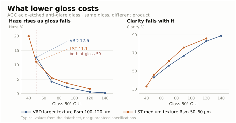
Now the table. The acid-etched AG glass AGC sells is a range divided by gloss, and the number after the product name is the 60-degree gloss itself.
| Product | Gloss | Haze | Clarity | Ra |
|---|---|---|---|---|
| VRD 50 | 50 | 12.6 | 43 | 0.58 |
| VRD 70 | 70 | 4.2 | 56 | 0.39 |
| VRD 90 | 90 | 2.2 | 67 | 0.25 |
| VRD 120 | 120 | 0.6 | 83 | 0.14 |
| VRD 140 | 140 | 0.3 | 89 | 0.10 |
| LST 40 | 40 | 20 | 33 | 0.38 |
| LST 50 | 50 | 11.1 | 46 | 0.26 |
| LST 70 | 70 | 5.5 | 61 | 0.20 |
| LST 90 | 90 | 3.6 | 76 | 0.13 |
| LST 120 | 120 | 1.7 | 86 | 0.08 |
Units: gloss in G.U. at 60 degrees, haze and clarity in percent, Ra in micrometers. The same document gives the texture spacing Rsm as 100–120 micrometers for VRD and 50–60 micrometers for LST.
Looking only at the VRD range, as gloss goes down from 140 to 50, haze rises fortyfold from 0.3 percent to 12.6 percent and clarity halves from 89 percent to 43 percent.
As much as glare is wiped out, the screen turns hazy and the image blurs. That nothing is free is the first thing this table says.
But the same table holds one more thing. Two products with the same gloss and different values.
VRD 50 and LST 50 both have a gloss of 50, but their haze is 12.6 percent and 11.1 percent, and their clarity 43 percent and 46 percent. LST buys the same glare suppression at a lower price.
The difference lies in the shape of the surface. VRD 50 has an Ra of 0.58 micrometers, while LST 50 has 0.26 micrometers, less than half. And Rsm, the mean spacing of the texture, differs by a factor of two, at 120 micrometers and 60 micrometers.
Roughness is not a single value. Height and spacing move separately, and each ruins something different. This distinction returns in Section 6.
Other details of this product family are noted here as well. The full range comes in sizes up to 1.60 by 3.21 meters and thicknesses from 0.4 millimeters to 6 millimeters. Single-sided or double-sided acid etching is available, and cutting, grinding, drilling, printing, thermal and chemical tempering, and wet coating can be added as post-processes.
The document itself carries a caveat: the values above are typical values, not guaranteed values, and are not suitable for use as specifications. Since the manufacturer attached this condition itself, it is carried over as is.
3. Why are there two ways to make the same AG?
AG splits into two manufacturing routes because of what the outermost layer of the screen is. Products with a cover window etch that glass. Products without one put a film or coating on top of the polarizer. The place it goes is entirely different.
Smartphones and tablets have a cover window on top of the panel. That glass is the exposed face, so AG means etching the glass.
This product class does not use AG much, though. The screen is held in the hand and its angle can be changed to dodge glare, and above all image quality comes first. A glossy face with only AF on top is the usual configuration.
Notebooks, monitors and industrial equipment are a different case. There is no cover window. The polarizer, the top layer of the panel, becomes the exposed face as it is, and a film or coating placed on top of it takes on AG.
The screen being fixed adds to that. Office ceiling lights do not move, and neither does a monitor. Those two things are why AG’s main market is here.
At this point the layer takes on one more job. Without a cover window, nothing protects the polarizer.
That is why one source, describing the AG film of LCD monitors, calls it an acid-etched plastic sheet and writes that the rough surface breaks up reflections while also protecting the front polarizer. One layer does two jobs.
The layers the industry lists as able to go on the polarizer base film are five: AG, HC, LR, AGLR and AR.
AGLR means anti-glare and low reflection combined in one layer. It also means that in products without cover glass, all four things covered in Part 2 sit on top of the polarizer.
The simple process is also a reason
There is one more reason a technology that loses on optics holds its place. Neither route uses vacuum equipment.
Glass etching is a single wet process of dipping into an acid bath, and film is a continuous process of unwinding from a roll, coating, curing with ultraviolet light and rewinding. There is no need to stack multiple layers and control thickness at the nanometer scale.
Durability comes from the same structure. An etched face is the glass itself, so there is no layer to peel off, and on film the hard coat layer is itself the AG layer, so a pencil hardness of 2H is specified along with the optical specs.
We could not find published price comparison figures, however. What the industry commonly holds to be cheap and confirming it in numbers are different things, so here only the process structure is described.
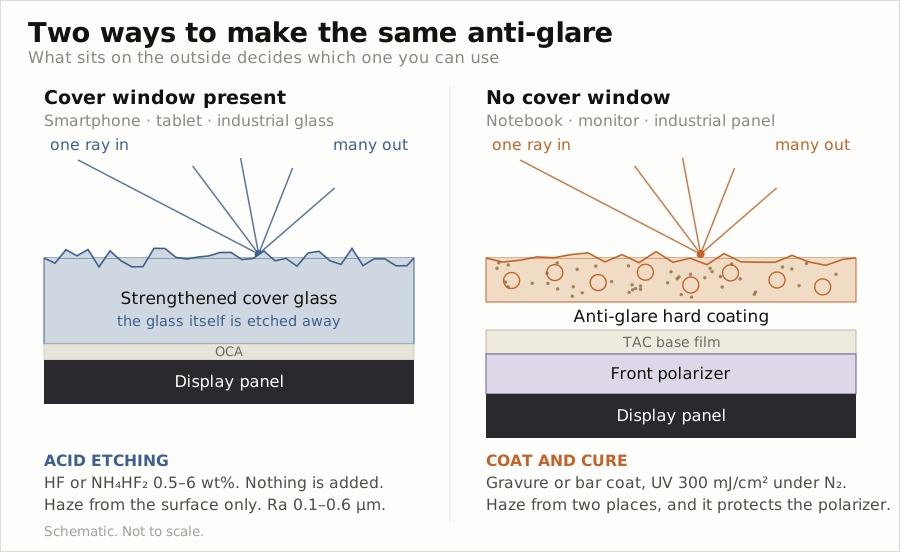
In short, AG is not one technology but two families. One cuts glass away, the other adds a film, and they differ in material, process and specification. The next section looks at each in turn.
4. Cutting away and laying on
The glass-etching side
It is acid etching. Glass particles are sprinkled onto the glass surface, which is then etched with a fluoride acid.
Where a particle sits the acid cannot reach, so the surrounding area is etched out first. As etching proceeds, the particles themselves are eroded and fall away, and in the process sharp peaks are worn down and softened. Creating roughness and smoothing it again happen within one process.
The acid is given as hydrofluoric acid or ammonium bifluoride, at a concentration in the range of 0.5–6 weight percent. The longer the etching time, the lower the gloss and the higher the haze. In other words, the vertical direction of the table in Section 2 is made by process time.
The process does not end when etching does. One published set of manufacturing conditions heats the glass at 680 degrees Celsius for 2 minutes and then quenches it after etching. It reads as a step that briefly softens the surface near the softening point of the glass to smooth out fine cracks and sharp tips.
The same source left values measured with the two routes side by side: etched AG at 9.3 percent haze and 90.7 percent transmittance, and film AG at 6.3 percent and 89.5 percent. The etched one has both higher haze and higher transmittance.
The target surface roughness is given as well. Ra of 0.2–0.7 micrometers, narrowly 0.3–0.6 micrometers, and texture spacing of 10–100 micrometers, narrowly 40–90 micrometers. The AGC measurements in Section 2 fall inside this range.
There are other routes besides acid etching: sol-gel spray coating, which sprays and cures a silica sol, and a method that lays down a layer with micrometer-scale particles dispersed in it. Since they build a new layer on the glass instead of cutting into it, they are closer to the film side that comes next.
The nature of this process becomes clear against the previous episode. AF was a matter of laying a molecular layer on the glass, and so it wore away as chains broke. An etched AG face is glass cut away, so there is no layer to peel off at all.
The film side
The composition is completely different. This is the anti-glare hard coat formulation disclosed by BenQ Materials of Taiwan.
The composition and process figures in this section are taken from specifications that film manufacturers filed and published. Which document each value comes from is noted in the source list at the end.
| Component | Content | Role |
|---|---|---|
| Acrylic resin | 75–90 parts by weight | Binder. Preferably 80–90 |
| Silica nanoparticles | 0.01–10 parts by weight | Primary particle size 5–30nm, secondary agglomerates 50–120nm |
| Organic microparticles | 5–20 parts by weight | Mean particle size 1–6μm, preferably 2–5μm |
| Leveling agent | 0.05–2 parts by weight | Surface smoothing |
That there are two kinds of particles is the key. Their sizes differ by as much as a hundredfold, and the two do different jobs.
Micrometer-scale organic particles are comparable to or larger than the film thickness, so they push up the film surface and create texture. These particles set the shape of the surface.
Nanoscale silica is far smaller than the film thickness and cannot push up the surface. Instead it stays inside the film and scatters light.
Here refractive index enters as a design variable. The range set for the refractive index of the organic particles is 1.0 to 1.60, while acrylic binders are generally around 1.5.
How far apart the refractive indices of particle and resin are set decides how much light scatters inside the film. Match them and the inside of the film becomes transparent. Separate them and it turns hazy. This is the knob that creates haze without touching the surface.
In high-haze grades the particles get larger. Another range from the same company uses amorphous silica microparticles, with a mean particle size by laser diffraction of 2–10 micrometers, a BET specific surface area of 60–100 square meters per gram, and 8–35 parts by weight per 100 parts by weight of acrylate binder.
The aim is shape. Instead of the smooth domes spherical particles make, they create irregular protrusions. Why that is done becomes clear in Section 6.
The typical base is TAC film. The triacetyl cellulose film used to protect polarizers becomes the base for AG as it is. The structure puts the AG function on that protective film while the polarizer is being made. PET, PEN and polycarbonate are also used as bases.
Coating is done by gravure coating or a bar coater. After the solvent is driven off, the layer is cured with ultraviolet light or an electron beam, under a nitrogen atmosphere at a cumulative 300 millijoules per square centimeter.
Nitrogen is used because oxygen inhibits radical polymerization. Curing in air leaves an unreacted layer at the surface and lowers hardness.
So this film carries pencil hardness alongside its optical specs. The measured value for both of the ranges above is 2H. In products without cover glass this layer has to protect the surface, so the requirement is a natural one.
5. Where does haze come from?
AG haze comes from two places: the surface of the film and the inside of the film. Etched glass produces all of it at the surface, but a film can split it between the two, for example by setting the surface share at 10–13 percent of a total haze of 40–50 percent. This distinction is the most important point in this episode.
The share arising from surface texture is called external haze, and the share arising from the refractive index difference between particles and resin inside the film is called internal haze. The sum of the two is the total haze written on data sheets.
The two paths bend light in different places. External haze arises from tilted normals at the boundary between air and film. Internal haze arises when light meets particles of a different refractive index inside the film.
Etched glass has no such distinction. There is only a surface, so all its haze is external haze. The only way to wipe out more glare is to make the surface rougher.
How to measure the two separately
No instrument measures the two separately. A haze meter gives only total haze. So you remove the surface and measure once more.
The method used in practice is this. An adhesive film with a haze value of 0 is applied to the coated face. The adhesive fills the valleys of the texture and flattens the boundary with air, so external haze disappears, and the value measured in that state is internal haze.
External haze is found by subtraction. It is total haze minus internal haze.
The measurement conditions are published too: the HM-150 haze meter from Murakami Color Research Laboratory, transmittance to JIS K 7361, haze to JIS K 7136, specimens of 4 by 4 centimeters, and the average of three measurements.
Why the method holds is explained by the principle from an earlier section. If the refractive index of the adhesive is close to that of the coating layer, light hardly bends at that boundary. The texture has been removed not physically but optically.
Each product splits it differently, and the spread is wide
Now the numbers. And here this episode’s finding takes its stand.
| Design | Split |
|---|---|
| Internal-weighted | Surface 10–13% of a 40–50% total |
| Surface-weighted | Internal 0.01–0.25 times total haze |
| Fixed ratio | External divided by internal 0.5–2 |
Both are film-type AG, yet the first two are opposites. One makes most of its haze inside the film. The other makes most of it at the surface. The latter holds the internal share below a quarter even as total haze rises from 39 percent to 93 percent.
The third takes a different approach. It sets the ratio itself as the specification, not the total: external haze divided by internal haze between 0.5 and 2, narrowly between 0.8 and 1.6.
And the party that set that range also spelled out what breaks at each end.
Below 0.5, the anti-glare effect becomes insufficient. And when this film sits under cover glass, the Newton-ring prevention that the external texture of the hard coat layer provided is reduced, and interference fringes appear.
Above 2, external haze grows, the sparkle produced by surface texture gets worse and clarity drops.
So this value is blocked both above and below. Push too far toward the inside and interference fringes come. Push too far toward the surface and sparkle comes. Given the same total haze, where to stand in between is the design.
The knob that moves the split
There is research showing it can be moved without changing materials.
Simply by changing the ratio of surface-treated to untreated scattering particles, with the composition of particles, resin and solvent unchanged, the ratio of external to internal haze can be moved from 0.32 to 3.14.
Surface treatment changes how well the particles disperse in the resin. Well dispersed, they stay evenly inside the film and produce internal scattering. Clumped, they rise to the surface and become texture. It amounts to changing the address of the haze with the same materials.
This range comfortably covers the 0.5 to 2 above on both sides. It means this is a knob that can actually be turned in the process.
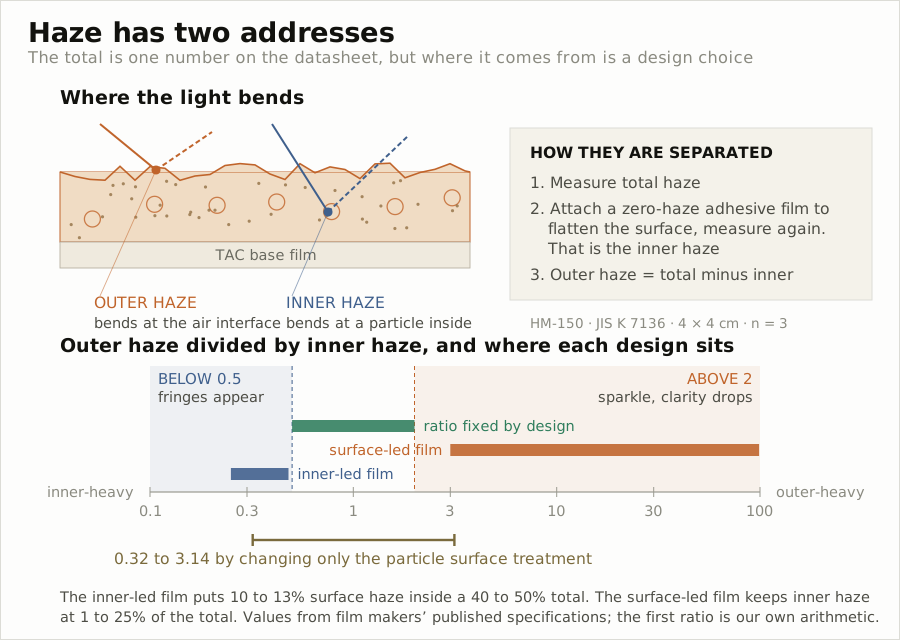
In short, for haze the design variable is not the total but the split. Two products may look the same on the single total haze figure in a data sheet, yet do different things on screen depending on where that value came from.
6. What catches on high resolution
Sparkle. It is the phenomenon in which, when a textured transparent surface overlaps a pixel array, bright, dark or colored spots appear at the scale of the pixel size. The screen looks grainy.
The cause is that the surface texture acts like tiny lenses in front of the pixels. Light from some pixels is concentrated and light from others is scattered, so pixels that should be equally bright end up uneven.
The condition under which it breaks is known. When the area of a diffusing particle becomes larger than the area of two adjacent pixels, light passing through the pixels is distorted and glittering spots appear. Uneven particle size and distribution cause the same problem.
Measurement
It is done with PPD, short for pixel power deviation.
A grid box is drawn around each pixel, the total power inside each box is measured with a CCD camera, and the value is the standard deviation divided by the mean, times 100. The measurement area Corning uses is about 30 by 30 pixels.
It matters that a reference display is written into the specification. PPDr, used to judge low sparkle, is measured on a TN-mode LCD with a native subpixel pitch of 60 by 180 micrometers.
That means the value is tied to the panel. The same glass shows different sparkle depending on the panel it goes on, so without a fixed reference no comparison holds.
The threshold offered is PPDr of about 6 percent or less. The condition Corning sets is PPD under 7.5 percent and an increase over the display alone of no more than 4 percentage points or no more than double.
A study checked whether this value matches the human eye
Having a measured value is no guarantee that it matches what is seen. So the Munsell Color Science Laboratory at Rochester Institute of Technology and Corning ran a psychophysical experiment together, published in a society journal in 2014.
Three things were reported. First, PPD correlates well with the sparkle people perceive. That is the basis for the measurement method above standing in for the human eye.
Second, with the same AG treatment, sparkle is worse on displays with denser pixels. The experiment confirmed that, for a given AG glass, which panel it goes on changes the result.
Third, sparkle measured on small specimens comes out more conservative than on full-size screens. Coupon tests come out worse than the real thing, which is the safe direction for judging.
The third is put to use directly in practice. It means there is no need to worry that a material passing on a small specimen will suddenly get worse on a large screen.
Not height but spacing
Here the Rsm from Section 2 comes back. AGC’s two ranges differ in Rsm. VRD is 100–120 micrometers and LST 50–60 micrometers, and the one with the reduced Rsm is named Low Sparkling Touch.
Published design guidance states the same relation directly. The texture spacing is kept in the range of 40–90 micrometers while being formed with the pixel pitch of the display taken into account. Pixel size enters as an input to texture design.
Sol-gel coating research points the same way. It reports that increasing the size of the polymerized species in the silica sol shortens the lateral pitch of the AG surface and lowers sparkle, while haze rises at the same time.
Try pushing only Rsm from 140 down to 20. The height stays the same and only the spacing of the peaks tightens. Then switch to the plan view and look at 110 and 50. At the former the texture clumps are larger than a pixel, and at the latter several bumps fit inside a single pixel.
Corning solves it the other way
Instead of random roughness it puts in periodic diffractive elements that spread light so that it fills the empty space between pixels.
The grating period is set as a function of pixel pitch, with the optimum at 3Dλ/Pitch. D is the optical distance from the pixel to the diffractive element, λ the wavelength, and Pitch the pixel size. Pixel pitch goes directly into the denominator.
The periods actually stated are 8.35–16.2 micrometers for notebooks and 19.8–39.6 micrometers for handheld devices. Surface specifications of an RMS amplitude of 80 nanometers or more and a total roughness of 60–600 nanometers apply as well.
A condition that holds the ratio of long-period to short-period components below 3.9 also applies. It means the specification is set on the period distribution, not on height.
The condition Corning offers for high resolution points the same way: transmission haze of 10 percent or less, PPDr of 6 percent or less and DOI of 80 or less, holding the total amount of haze itself low.
So the split in Section 5 pays off
Because it is surface texture that produces sparkle, putting the same haze on the inside can wipe out glare while producing less sparkle.
A manufacturer attributes the sparkle resistance of high-haze AG film to eliminating the lens effect of the surface. The irregular protrusions seen in Section 4 serve the same purpose: keeping light from coming to a focus.
But as Section 5 showed, the haze cannot be pushed inward without limit. When the ratio of external to internal falls below 0.5, interference fringes come instead. The narrow band between sparkle and interference fringes is this film’s design space.
7. The makers have changed
On the film side, Japanese and Taiwanese companies are at the center. At Nitto Denko, optical films account for 55 percent of revenue, and DNP produces AG and LR films together. The composition figures seen earlier came from BenQ Materials of Taiwan.
Beyond them, 3M, Mitsubishi Chemical, Toppan, Lintec and Covestro are named as suppliers. On the glass side it is AGC and Corning.
Korean companies are dropping off this list. To be precise, they have already left.
What happened in five years
| Date | Deal | Size |
|---|---|---|
| 2020-06 | LG Chem LCD polarizer business → Shanshan, China | about 1.3 trillion won |
| 2023-09 | LG Chem polarizer business → Shanjin Optoelectronics | 269 billion won |
| 2023-09 | LG Chem polarizer materials business → Hefei Xinmei Materials | about 829.2 billion won |
| 2024-09 | Samsung SDI polarizing film business → Wuxi Hengxin Optoelectronic Materials | 1.121 trillion won |
The item list for the September 2023 sale includes surface treatment film for automotive displays. TAC film for LCD polarizer protection and PET film for cover windows are on it as well. The layer this episode covers is on that list.
On the Samsung SDI side, the entire polarizing film manufacturing and sales business at the Cheongju and Suwon sites and all shares in the Wuxi subsidiary in China were transferred. The buyer, Wuxi Hengxin, is a joint venture of Nuoyan Capital and its polarizing film affiliate.
In the same period SKC sold its film and processing business for 1.6 trillion won, and Hyosung Chemical and Kolon Industries scaled back their film businesses. The reason the industry gave was that low-priced volume from China made it hard to maintain profitability.
What went over was not only equipment and people. The design specification from Section 5 that set the external to internal haze ratio at 0.5 to 2 came out of Korea, and the rights to it now sit with the acquirer. The inventors all have Korean names, and it was filed in 2018.
And that company built a large production line for polarizer surface treatment film in September 2025. Demand for high-performance optical film for automotive head-up displays and smartphones is cited as the reason for the expansion.
The sellers gave as their reason shifting resources to battery materials, eco-friendly materials and new drugs. The buyer is expanding on that same ground. The same business, judged two different ways.
What remains in Korea is on the coating side. Dongwoo Fine-Chem, a subsidiary of Sumitomo Chemical, is known to perform coating in Korea with base film supplied from Taiwan. We could not find market share figures for Korean AG film suppliers.
8. What lies ahead
Weight shifts to vehicles
A vehicle interior has every condition for AG. The lighting position cannot be chosen, sunlight comes in directly, and the screen is fixed so angles cannot be avoided.
An industry source writes that chemical acid etching is the industry standard for automotive cover glass. It adds that the aim is to create a uniform microstructure that eliminates reflection while also preventing sparkle and pixel shimmer.
This means the two demands seen in Section 6 apply together in vehicles from the start. Handling glare alone is not enough. Sparkle has to be prevented at the same time.
The readability bar is high too. 800 nits or more, typically 1,000 nits, is cited as the brightness readable in sunlight, and a head-up display needs 15,000 nits or more as the value reaching the eye after reflecting off the windshield.
Brightening the screen and scattering reflection are required at the same time. Neither alone beats sunlight.
On top of that come pillar-to-pillar large screens and curved surfaces. Etching curved glass uniformly, meeting crash safety standards at the same time, and preserving three-dimensional form remain to be solved.
Resolution keeps rising
Convert AGC’s product ranges into terms of texture spacing and a trend shows. VRD’s Rsm of 100–120 micrometers corresponds to 212–254ppi as a pixel pitch, and LST’s 50–60 micrometers corresponds to 423–508ppi.
It reads as a story of product generations getting finer to follow resolution.
The direction itself is supported by the sources. The psychophysical experiment in an earlier section reported that with the same AG treatment, sparkle is worse the denser the pixels, and published design guidance also says to set the texture with pixel pitch taken into account.
The conversion above, however, is our own. Assigning a ppi by turning Rsm into a pixel pitch is a calculation, and AGC has never stated that it divided its ranges to target those resolutions. The association is as far as the sources go, and the product planning intent is an inference.
AGC has one more range beyond LST, called NST. It stands for No Sparkling Touch, and the document states that it has been supplied in the full size range since September 2016.
But the performance table does not list NST figures. It appears only as a curve on the graph of gloss against clarity, from which all that can be read is that its clarity is higher than VRD and LST at the same gloss. We searched but found no published figures.
Where it overlaps with the previous episode
AG makes fingerprints less visible. A high-gloss face returns light uniformly, so oil marks stand out, but on a matte face those marks cannot create sharp reflections.
This connects with what the previous episode covered. What decides how visible a fingerprint is is the gloss difference between residue and surface, and AG lowers the gloss on the surface side to narrow that difference.
Where AF makes oil bead up, AG makes it less visible even when it sticks. The same problem, solved another way.
That is not the reason for using AG, though. If fingerprints are the goal you use AF, and in practice AF is put on top of AG faces too. Several layers going on the same face, each for its own reason, is the pattern that repeats through this part.
The next episode covers another layer on the same face. Instead of scattering reflection, it cancels it.