Surface Treatment: AR (Anti-Reflection) and LR (Low-Reflection)
Cancelling reflection with one layer on glass calls for a material of refractive index 1.23, and no dense solid reaches it. LR approaches that value through the voids inside hollow silica, while wet-coated and sputtered AR stacks give up on index and cancel by interference instead. Both are designed against air, so when oil lands on them the stack that erased reflection most deeply is the one that fails hardest.
The layer covered in the AG episode scattered reflection. It left the little over 4 percent that the front face of the glass returns untouched and only spread its direction wide. The layer in this episode reduces that 4 percent itself.
Two routes are used on films and on cover glass. LR, which wet-coats a low-index material, and AR, which stacks oxides of differing refractive index many layers deep.
An SID commentary from 2013 sums the two up this way. LR is cheap to make but its reflection is not low enough, while AR reflects little but costs more to produce. This episode looks at where that difference comes from, in material and in stack.
Both diverged from the same blank. A material of refractive index 1.23 is needed, and no such solid exists. What that blank is, and what the fact that air created it means the moment a fingerprint lands, is the spine of this piece.
1. What material it takes to cancel reflection
Cancelling reflection with a single layer on glass takes a material of refractive index 1.23. That value is the square root of air at 1.00 multiplied by glass at 1.52, and no dense solid reaches it. Magnesium fluoride, the lowest dense inorganic film there is, sits at 1.38.
The principle is to have two reflections cancel each other. Put a thin layer on and light comes back once at the boundary between air and the layer, and once at the boundary between the layer and the glass.
Set the layer thickness to a quarter of the wavelength of the light and the second reflection, making a round trip through the layer, falls half a wavelength behind. The two reflections end up opposite in phase. If their magnitudes match as well, the two cancel exactly.
For the magnitudes to match, the ratio of refractive indices at the upper and lower boundaries has to be the same. The point where the ratio of air to layer equals the ratio of layer to glass is 1.23. How reflectance is set at a boundary was covered with glass and skin in the episode on optical fingerprint sensors.
Computed under the same conditions with only the index of the single layer varied, photopic reflectance Y comes out as follows. Glass at 1.52, normal incidence, quarter-wave thickness referenced to 550 nanometers.
| Index of the single layer | What it is | Photopic reflectance Y |
|---|---|---|
| none | bare glass | 4.26% |
| 1.46 | dense SiO₂ | 2.83% |
| 1.38 | MgF₂, the floor for dense inorganic films | 1.30% |
| 1.35 | hollow silica film | 0.87% |
| 1.30 | low-index layer with more voids | 0.34% |
| 1.23 | target value | 0.06% |
A single MgF₂ layer stops at 1.30 percent. That is a third of bare glass at 4.26 percent. Going lower means either making a material close to 1.23 or giving up the single-layer condition.
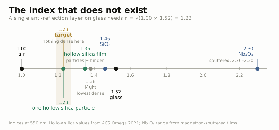
So anti-reflection technology split in two directions. LR puts holes in the material to approach 1.23, while AR gives up on refractive index and stacks layers to cancel by interference. Sections 3 and 4 take them in turn.
A third route, raising nanoscale bumps on the surface to grade the refractive index, is taken up separately in next issue’s Surface Treatment: Moth-Eye.
2. How reflectance is measured
The first line of an anti-reflection data sheet is photopic reflectance Y. It reduces reflectance measured wavelength by wavelength to a single value by weighting it with the sensitivity of the human eye and the distribution of the light source, and it is computed as the reflective stimulus value Y of JIS Z 8701.
Eye sensitivity peaks near 555 nanometers and falls off steeply toward both ends. So Y is sensitive to green reflection in the middle and dull to blue and red reflection at the edges. In Section 4 this property is what produces reflected color.
There is one trap in the measurement. A glass plate returns 4 percent from its back face as well. Measuring only the AR on the front means getting rid of the back reflection.
The measurement conditions AGC discloses are to paint the back of the glass with black lacquer to erase the back reflection, measure the spectrum with a Shimadzu spectrophotometer and convert it to Y. Skip that step and the 4 percent off the back rides on top, so even a 0.3 percent AR reads in the 4 percent range.
SCI and SCE are attached to the sheet as well. They distinguish whether the specular component was included in the measurement or excluded. On a smooth AR face reflection is almost entirely specular, so SCI is what gets written. On a face mixed with AG the two diverge.
Finally the reflected color a* and b* is attached. If reflectance is uneven across wavelength the remaining reflection takes on color, and that color is written in L*a*b* coordinates. A negative b* means a blue cast.
The reflection this layer reduces is the one at the very outside of the screen. The POL-less structure seen in the ALS episode suppresses reflection off the metal electrodes inside the panel, so it sits somewhere else.
In OLEDs a circular polarizer blocks the inside reflection. An ideal circular polarizer brings ambient reflection down to the reflection off the first surface of the polarizer itself. Once the inside is suppressed, what remains is exactly the one outer face this episode deals with.
What that difference in reflectance amounts to on screen comes out of arithmetic. Under uniform ambient brightness the luminance the surface returns is reflectance times illuminance divided by π, and it adds equally to the white screen and the black screen alike.
The calculation assumes a panel at 500 nits white and 0.5 nits black. Under an evenly overcast outdoor 10,000 lux, bare glass gives a contrast ratio of 4.7 to 1, LR at 0.87 percent gives 18.7 to 1, and an AR at 0.29 percent reflectance gives 52 to 1. At 500 lux in an office, 70 to 1 rises to 520 to 1.
Lowering reflectance from 4.26 percent to 0.29 percent is, under these conditions, the same as raising screen brightness about 15 times. When reflected luminance is far larger than the black screen, contrast ratio is set by the ratio of brightness to reflectance alone. The contrast simulator in the AG episode took 3 to 1 as the limit of legibility.
3. LR, approaching 1.23 with holes
LR reduces reflection by wet-coating a single layer of low-index material. The material used here is hollow silica, silica particles that are empty inside. Silica itself is 1.45, but hollowing it out pulls the average refractive index of the whole particle down toward air.
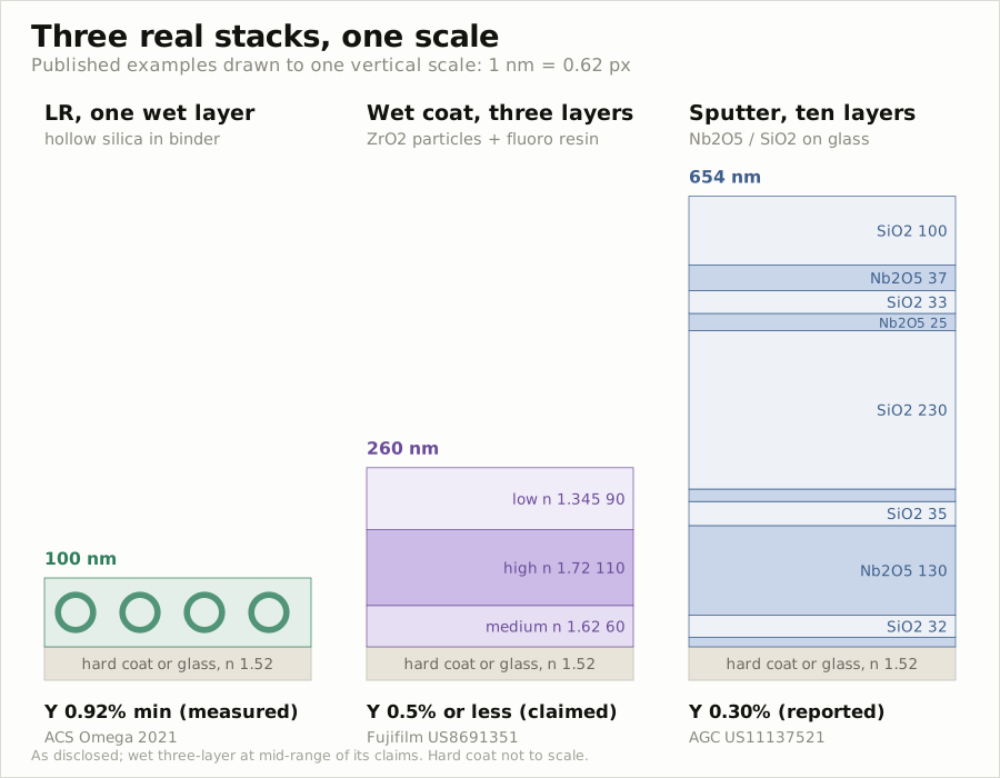
The particles used in the 2021 ACS Omega work are about 60 nanometers in diameter, with a shell 8 to 10 nanometers thick and a particle refractive index of 1.23. A single particle lands exactly on the target value.
Made into a film, though, it becomes 1.35. Particles alone do not make a film. A resin that holds the particles fills the gaps between them, and that resin pulls the average refractive index back up.
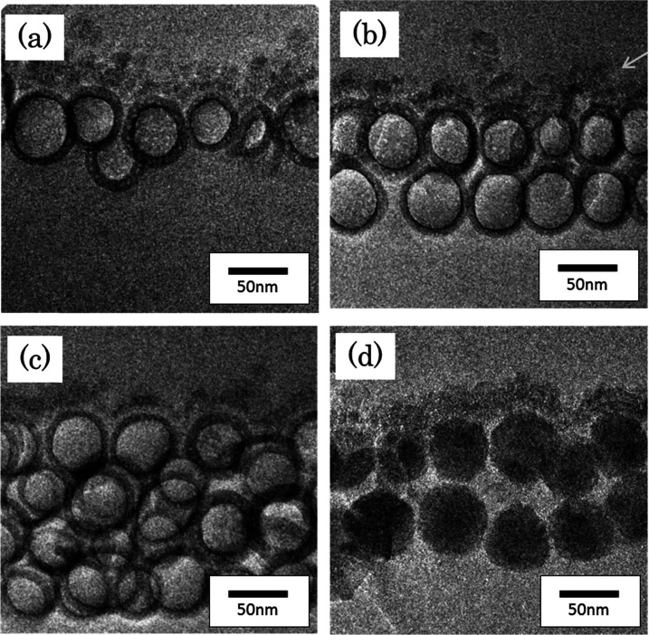
The measured minimum reflectance of this film is 0.92 percent at 550 nanometers. The control made with solid silica particles came in at 3.96 percent. Computed under the same conditions as the Section 1 table (index 1.35, quarter-wave thickness), the value at the design wavelength is 0.82 percent, so allowing for the difference in substrate the two line up. The 0.87 percent in the Section 1 table is the same film weighted by the eye response, which sits a little above the minimum.
The same work compared particles stacked one layer, two layers and three to four layers deep, and a film of about 100 nanometers made of two staggered layers was the best of them. Total light transmittance 95.2 percent, haze 0.22 percent.
Why two layers is the right answer lies in the thickness condition from Section 1. The quarter-wave thickness of a film at refractive index 1.35 is 102 nanometers referenced to 550 nanometers. A single row of 60-nanometer particles falls short, while two rows staggered and overlapped reach that thickness. Particle size is what sets film thickness.
The process is the same family as the film in the AG episode. Curing under 400 millijoules per square centimeter of ultraviolet in a nitrogen atmosphere with oxygen below 100 ppm, drying at 80 degrees, and the whole process stays under 100 degrees. The substrate is TAC.
Which means an LR layer can be coated once more on top of an AG layer on the same line. This is where AGLR, named but not detailed in the AG episode, comes from: a film that is anti-glare and low-reflection at once.
The particles are sold by material makers as grades. The hollow silica THRULYA 4110 from JGC Catalysts and Chemicals is listed in published specifications with a particle refractive index of 1.25, and its particle size is given as 50 to 60 nanometers depending on the document.
Lowering the particle index further means hollowing it out further. At the same particle size, hollowing it out thins the shell, so the knob that lowers refractive index and the knob that preserves particle strength are the same knob.
Strength is in fact the weak point. The film in the work above measured pencil hardness H on a hard coat, and on bare TAC it did not even reach 6B. A low-index layer on its own cannot protect the surface and leans on the hard coat beneath it.
Mixing particles of different sizes
A formulation that holds strength together with reflectance has been disclosed as well. The low-index layer LG Chem filed mixes hollow silica of 40 to 60 nanometers diameter with hollow silica of 65 to 100 nanometers at a ratio between 7 to 3 and 3 to 7, and adds solid silica of 15 to 18 nanometers diameter together with a fluorine compound.
The arrangement puts the small hollow particles into the gaps between the large ones. The average reflectance of this film from 380 to 780 nanometers went from 0.69 percent to 0.71 percent after rubbing, essentially unchanged.
It held up against scratching too. The steel wool load at which no scratch appeared rose from the comparative example’s 200 grams to 500 grams. The design sets out to block the rise in reflectance under rubbing through particle size distribution.
Wet-coating three layers
The limit of a single layer is around 1 percent. One layer of a 1.35 film gives 0.9 percent, and even taken down to 1.30 it is in the 0.3 percent range. Going lower means adding layers on the wet side too.
The anti-reflection film Fujifilm disclosed coats three layers in turn onto a hard coat 1 to 30 micrometers thick on TAC. A medium-index layer at 1.60 to 1.64 and 55 to 65 nanometers, a high-index layer at 1.70 to 1.74 and 105 to 115 nanometers, and a low-index layer at 1.32 to 1.37 and 85 to 95 nanometers.
The material that raises refractive index is metal oxide fine particles such as zirconium oxide. Particles 1 to 120 nanometers in diameter go into the resin to make the medium- and high-index layers, while the low-index layer mixes hollow particles of refractive index 1.17 to 1.40 into a fluorine-containing curable resin. Curing is done at an oxygen concentration of 10 volume percent or below.
The target is an average specular reflectance of 0.5 percent or below. Computed at the midpoints of the ranges, photopic reflectance comes to 0.27 percent, inside the target. Combine the extremes of the claimed ranges and it moves between 0.08 and 0.87 percent.
Three wet-coated layers drop below a third of a single LR layer. DNP likewise states that it makes reflectance down to 0.1 percent with a maximum of three wet layers. Metal oxide particles in resin stand in for the Nb₂O₅ of the sputtered AR in Section 4, and wet coating with layers added crosses over, in principle, into interference-type AR.
4. AR, going by interference instead of refractive index
AR does not go looking for 1.23. It alternates two materials with widely different refractive indices and sets the thicknesses so that the reflections coming back from each layer cancel one another.
The combination mostly used for display AR is Nb₂O₅ and SiO₂. Sputtered Nb₂O₅ is reported at a refractive index of 2.26 to 2.30 at 550 nanometers, while SiO₂ is 1.46. The gap is large, so fewer layers can do the cancelling.
Look at a real stack. The anti-reflection film AGC disclosed runs, from the glass side, Nb₂O₅ 14 · SiO₂ 32 · Nb₂O₅ 130 · SiO₂ 35 · Nb₂O₅ 18 · SiO₂ 230 · Nb₂O₅ 25 · SiO₂ 33 · Nb₂O₅ 37 · SiO₂ 100 nanometers, ten layers totalling 654 nanometers. It is laid down by magnetron sputtering.
The measured photopic reflectance is 0.30 percent (JIS Z 8701, D65 illuminant, 10-degree observer). The same specification also records near-infrared transmittance from 700 to 950 nanometers at a minimum of 89.5 percent. It is a design that writes near-infrared into the specification, not visible light alone.
Computing directly from the disclosed thicknesses gives 0.16 percent, about half the published value. This calculation leaves out dispersion, the variation of refractive index with wavelength, and absorption, so it is used for order and shape rather than absolute value. Put the layers in reverse order and it comes out at 8.43 percent, worse than bare glass. Same materials, same thicknesses, and the order is the design.
That the top is SiO₂ at 100 nanometers is worth marking as well. Put the low-index oxide at the very outside and the refractive index step against air is at its smallest. The specification states that laying a fluorine-containing organosilicon anti-smudge layer on top of that is preferable, and the silica face the silane head bonds to, seen in the AF episode, is exactly this layer.
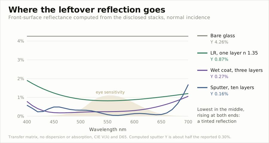
The simulator below lets you change the four layer thicknesses yourself and watch how this curve moves. The switch that turns the top into oil is used in Section 5.
In Figure 4 the sputtered 10-layer stack is 0.08 percent at 550 nanometers, nearly zero in the middle, while both ends spring up. It is 0.58 percent at 400 nanometers and 1.69 percent at 700 nanometers. The wet-coated 3-layer stack has the same shape. The design pushes the remaining reflection out to the edges where eye sensitivity is low.
The reflection pushed out remains as color. The data sheet for Dexerials’ automotive AR film AR100 records that trace.
| Item | Value | Test standard |
|---|---|---|
| Photopic reflectance Y (SCI) | 0.29% | JIS Z 8701 |
| Total light transmittance | 96.2% | JIS K 7105 |
| Haze | 0.3% | JIS K 7105 |
| Reflected color a* / b* | 1.6 / −6.7 | SCI |
| Water contact angle | 120° | JIS R 3257 |
| Steel wool 1,000gf, 150 strokes | no scratching |
The reflected color of this film is b* −6.7, a blue cast. It means the light left on a face of 0.29 percent reflectance leans toward blue. Suppress the middle and leave the edges and that is what happens.
Interference is weak against angle. When light enters obliquely the optical path through the layers shortens and the design wavelength slips. Computed by angle of incidence, the disclosed stacks come out as follows. The two polarizations were averaged.
| Angle of incidence | 0° | 30° | 45° | 60° |
|---|---|---|---|---|
| Bare glass Y | 4.26% | 4.41% | 5.30% | 9.25% |
| Single LR layer Y | 0.87% | 0.98% | 1.62% | 4.71% |
| Wet-coated 3-layer Y | 0.27% | 0.45% | 1.16% | 4.35% |
| Sputtered 10-layer Y | 0.16% | 0.27% | 1.03% | 4.47% |
The sputtered 10-layer stack is six times its head-on value at 45 degrees and at 60 degrees it passes the head-on value of bare glass, 4.26 percent. The stack that was lowest head-on because it had the most layers comes to resemble a single LR layer when seen obliquely.
As the angle grows, the red end springs up first. The 700-nanometer reflectance of the sputtered 10-layer stack rises from 1.69 percent head-on to 3.96 percent at 30 degrees and 7.45 percent at 45 degrees. Reflection that was blue head-on shifts toward red when seen obliquely. It is a property that shows itself in places like a centre automotive display, viewed off-axis from both the driver’s and the passenger’s seat.
For film the process is roll-to-roll sputtering. The film is unwound from a roll and passed through a vacuum chamber while the oxides go on in turn. It is a process that has to hold nanometer-scale thickness across a whole roll of film. For cover glass, the glass plate goes into the chamber and the same magnetron sputtering lays the layers down.
This process is concentrated in one company. On the basis of a 2025 Fuji Chimera Research Institute report, Dexerials held 92.8 percent of the world market for sputtered anti-reflection film on a 2024 value basis. It has been first for six consecutive years since 2019.
There is also AR that adds absorption to interference. An anti-reflection film AGC disclosed is three layers of SiO₂ 20 nanometers with silver fine particles dispersed in it, TiO₂ 25 nanometers and SiO₂ 120 nanometers. The silver particles eat some of the light.
The conditions on this film come as one bundle: photopic transmittance of 20 to 85 percent, photopic reflectance of 1 percent or below, b* of 5 or below against a D65 illuminant, and sheet resistance of 10⁴Ω/□ or above. It lowers reflection while deliberately darkening, and it writes reflected color and electrical resistance into the specification alongside.
A layer that darkens also weakens the light coming back out from inside the panel, since that light passes through twice. Unlike a transparent AR, which deals only with the one outer face, the absorbing type moves to suppress the inside reflection as well.
5. Why one fingerprint breaks the best AR hardest
Because both methods were designed against air. The target value of 1.23 is a value air set, and when oil sits where the air was the design becomes the wrong design. Assuming a smooth oil film and computing with the disclosed stacks, reflectance at the smudged spot against the clean spot is 0.9 times for bare glass, 5 times for a single LR layer, 22 times for the wet-coated 3-layer stack and 39 times for the sputtered 10-layer stack.
For imitating fingerprint oil, the design material Corning published uses a refractive index of 1.4 to 1.6 with a representative value of about 1.49. This episode takes 1.47 as its reference and computed 1.43 and 1.50 alongside it.
With oil at 1.47 sitting on top, the target value moves to 1.49, the geometric mean of oil and glass. That is effectively a condition in which no anti-reflection layer is needed, and a layer designed against air becomes an obstacle under it.
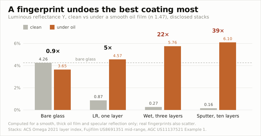
The reason the stack with the most layers breaks the hardest is that the layers remain. Covered in oil, the five Nb₂O₅ layers inside the film are still there. With their surroundings changed from air to oil, those high-index layers now turn into reflectors.
The result is that the covered sputtered 10-layer stack reads 6.10 percent and the wet-coated 3-layer stack 5.76 percent, both higher than clean bare glass at 4.26 percent. The smudged spot is not only tens of times brighter than its surroundings, it is brighter than uncoated glass.
Change the refractive index of the oil and recompute and the order stays the same.
| Photopic reflectance once covered | Oil 1.43 | Oil 1.47 | Oil 1.50 |
|---|---|---|---|
| Bare glass (clean 4.26%) | 3.22% | 3.65% | 4.00% |
| Single LR layer (clean 0.87%) | 3.85% | 4.57% | 5.13% |
| Wet-coated 3-layer (clean 0.27%) | 4.93% | 5.76% | 6.40% |
| Sputtered 10-layer (clean 0.16%) | 5.25% | 6.10% | 6.76% |
In every oil the order is the order of layer count. Which means the conclusion does not hang on a single value for the refractive index of oil.
Only bare glass, at 0.9 times, is nearly unchanged. The oil in fact lowers reflection a little. So the reason a fingerprint shows on bare glass is not reflectance. As seen in the AF episode, it is the scattering the oil makes as it breaks into beads and films.
On AR a fingerprint shows even without scattering. A smoothly spread smudge is enough, because reflectance jumps tens of times. The same fingerprint is visible on bare glass and on AR by different mechanisms.
Stand View tilt up to 5 degrees and the ceiling lights on the sputtered 10-layer stack stay dark blue squares while only the fingerprint floats up as a white smear. At about 9 degrees in the middle of the screen the clean face is 0.15 percent and the covered spot 6.1 percent, a factor of 40.
Lay it down to 60 degrees and the checkerboard of lights brightens to pink and the fingerprint is nearly buried. That is because the clean face rises to 4.0 percent and the multiple falls to 2.7. A fingerprint on AR is most visible head-on.
Press Bare and the lights spread into white squares, and the fingerprint spot, rather than rising, goes slightly darker. It matches the calculation above, that on bare glass oil lowers reflection to 0.9 times.
The industry treats this multiple as a design variable. The design material Corning published defines contrast as the average reflectance in a medium imitating oil divided by the average reflectance in air, and offers film configurations that lower that contrast. The medium is taken as a flat layer 100 to 2,000 nanometers thick.
Scratching appears in the same material. It states that on a usual AR coating, a spot where scratching has taken 25 to 500 nanometers of coating away has a contrast of about 100 or more. Whether oil covers it or the coating is stripped off, a spot where the design has broken is tens of times brighter than its surroundings.
A screen protector erases AR on the same principle, because the adhesive takes the place of the air. Measured at 20 degrees of incidence by a protector vendor, the values were 2.1 percent for the iPhone 17 and 4.6 percent with an ordinary protector on it.
In the same measurement the iPhone 16 Pro, which had no AR, was 3.8 percent. It is a vendor measurement with no light source or sensor specification disclosed, so it is read for direction rather than magnitude. Put an ordinary film on AR and it is brighter than it was before the AR.
Go back to the simulator in the previous section and turn the top into oil, and the same thing happens in front of you.
Press Oil smudge on the 4-layer AR and the blue curve disappears while the orange curve climbs above the dashed line for bare glass. Switch to Bare and the reverse is visible, the oil lowering reflection a little.
Press 1 layer to leave a single SiO₂ layer of 94 nanometers and it is 2.83 percent clean and 3.67 percent covered, a factor of only 1.3. The thinner and fewer the layers, the less it breaks; the more deeply it erases reflection, the harder it breaks. Take the middle Nb₂O₅ thickness down to 0 and the move between the two is visible.
6. And so AF goes on top of AR
For AR to deliver its performance, oil must not stay on it long. Which is why an AF layer goes on top of AR films and AR cover glass. The water contact angle of 120 degrees in the AR100 data sheet is that layer’s value.
The AF layer is optically almost absent. As seen in the AF episode, at a thickness on the order of 10 nanometers it does not disturb the AR design and can be laid on top.
The problem is lifetime. In 2022 Dexerials released its HD series, with the anti-smudge layer on top of the AR film changed from wet coating to vacuum deposition. It held a water contact angle of 110 degrees or above through more than 20,000 cycles of nonwoven-cloth rubbing, and the company stated abrasion resistance was more than 40 times that of the previous version.
The conclusion of the AF episode carries through to here. That episode held that wear begins where the chains at the surface break, and the initial contact angle does not represent performance. When the AF on top of AR wears down, oil begins to spread, and spread oil shows at the multiples of Section 5.
So AR film data sheets carry two abrasion tests. One rubs with steel wool at 1,000gf for 150 strokes and looks for scratching, the other measures contact angle after tens of thousands of wipes with nonwoven cloth.
The two measure different failures. Steel wool looks at whether the oxide layers get scratched and stripped, while nonwoven rubbing looks at whether the AF chains on top wear away. Break the first and you get the scratch contrast of 100 or more from Section 5; break the second and oil spreads and you get the fingerprint multiples.
Automotive is where this demand weighs heaviest. Citing the fact that cars are used for more than 10 years, Dexerials emphasises the ultraviolet and high-temperature durability of its AR film and publishes reliability data at high temperature for 1,000 hours. The HD series was aimed at automotive as well as notebooks and 2-in-1 devices.
In vehicles an AR film does more than suppress reflection. Dexerials also cites the role of holding the fragments together so they do not scatter when the cover glass breaks. It is a requirement that arrived as the screen in front of the driver rose above the dashboard and grew.
The timing of that shift is on record as well. Dexerials writes that the design change of enlarging in-vehicle screens and mounting them high began with European carmakers in the late 2000s and settled in worldwide by the mid-2010s. The closer the screen rises to the driver’s line of sight, the heavier both reflection and fragments become.
7. Who publishes reflectance numbers
The ones that publish reflectance numbers are film companies and material makers, in their published specifications; the ones that do not are smartphone cover glass announcements. Dexerials’ data sheets and the specifications from AGC, Fujifilm and LG Chem write reflectance as a number. Corning’s and Apple’s announcements did not put out absolute values.
Of Gorilla Glass DX+, which went into the Galaxy Watch in 2018, Corning announced that it reduces front-surface reflection by 75 percent against ordinary glass and raises contrast ratio by 50 percent at the same brightness. It added that the optical improvement could also help battery life.
The Gorilla Armor announcement for the Galaxy S24 Ultra in 2024-01 also carries a reduction in reflection of up to 75 percent against the surface of ordinary glass. It is the same number as DX+ for the watch. The basis is in-house laboratory testing, and neither announcement gives an absolute reflectance.
Apply a 75 percent reduction to bare glass at 4.26 percent and a little over 1.1 percent is left. That value is this magazine’s arithmetic, not a figure Corning wrote.
In 2025-09 Apple introduced Ceramic Shield 2 on the iPhone 17 Pro as “3x scratch resistance, improved anti-reflection.” No reflectance number appears in the announcement. The 60 percent reduction and seven-layer coating some outlets carried could not be found in Apple’s announcement.
The same announcement puts forward 3,000 nits of peak outdoor brightness and twice the outdoor contrast ratio. By the arithmetic of Section 2, outdoor contrast ratio is set by two knobs, brightness and reflectance. Apple stated only that it turned both knobs and did not write out the share of each.
Film is sold as a component and the data sheet becomes a term of the transaction. Cover glass performance goes out as wording in a finished-product announcement. Where the numbers part overlaps with that difference.
In Korea there are coating processors advertising AR glass coating, but no domestic company was found publishing an anti-reflection film market share figure. How the polarizer and surface treatment film businesses moved offshore was covered in the AG episode.
Reduced to three lines, this episode goes as follows. The target refractive index of 1.23 for anti-reflection is a value air set, and LR substitutes for that missing material with holes while AR substitutes for it with layers and interference. And so, when oil sits where the air was, the more deeply a stack erased reflection the harder it breaks.
The next issue takes up the third route, moth-eye, which turns the surface itself into a gradient of refractive index.