
Surface Treatment: AF (Anti-Fingerprint)
An AF coating does not stop fingerprints from landing. It only stops them from spreading. Two products from the same maker sit at 116 and 109 degrees of water contact angle, almost the same, while their steel wool abrasion counts split four to one at 24,000 and 6,000. Material structure, deposition routes, measurement standards and where the wear actually happens, traced through manufacturer technical data sheets.
Hold a phone at an angle without turning it on and the fingerprints show. Rub it on a shirt a few times and it mostly comes clean. Set against the grease on a drinking glass, which a dry cloth barely lifts, that is an odd result. The same oil from the same finger, and a different outcome.
What makes the difference is a layer of about 10 nanometers sitting on top of the cover window. The industry calls it AF, anti-fingerprint coating. The name reads as though it keeps fingerprints off, but that is not what the layer actually does.
This episode walks one layer from material to specification. What it is made of, how it is laid down, what it is measured with, and why it wears out. Along the way one conclusion lands straight in practice. An AF coating cannot be chosen by contact angle. Why that is so is the spine of this piece.
1. What comes off a fingertip
Two things transfer when a finger touches glass. One is sweat from the eccrine glands, the other oil from the sebaceous glands.
Eccrine secretion is mostly water. The composition given in the literature is 98.5 to 99.5 percent water and 0.5 to 1.5 percent solids, with salts, amino acids and urea among the solids. Water evaporates and leaves a thin film of salt. So it is not the water side that decides how a fingerprint looks.
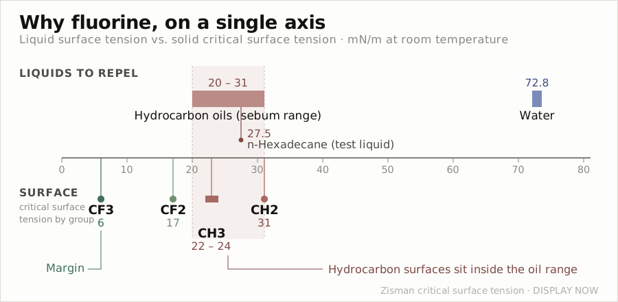
What stays is the oil. Sebum is made of fatty acids, wax esters and squalene, and its surface tension is low. Hydrocarbon oils generally fall in the range of 20 to 31 millinewtons per meter. For comparison, water is 72.8 under the same conditions. n-Hexadecane, often used in testing, sits at 27.5, which places it well for standing in for sebum.
The glass on the other side has high surface energy. Cleanly washed glass wets so well that even water lies almost flat on it. When a low surface tension liquid meets a high surface energy solid the outcome is settled. The liquid spreads. Rather than staying a droplet where the finger landed, it becomes a thin film and creeps sideways.
That raises a second question. Why is a spread oil film visible at all? The oil itself is colorless and transparent.
It is visible because the film has a refractive index different from the glass and its thickness is uneven. Light crossing two interfaces, air to film and film to glass, produces reflections, and because film thickness varies from place to place so does the amount of reflection. Uneven gloss is the result. That is why literature on fingerprint visibility also lists reducing the difference in gloss and refractive index between residue and surface as a countermeasure.
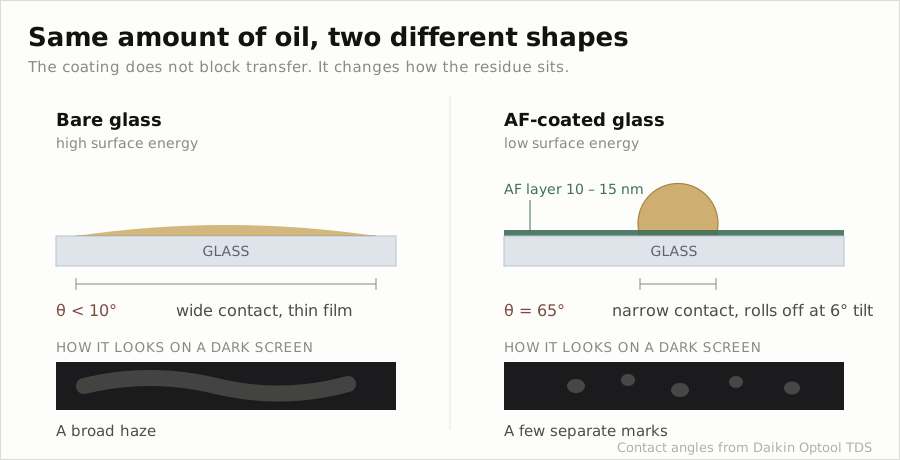
Put together, the fingerprint problem is not a problem of how much lands but a problem of how far it spreads. The same amount beaded up is a few dots. Spread into a film, it hazes one whole side of the screen. And that distinction explains exactly what an AF coating is.
2. What an AF coating actually does
This layer cannot stop oil from landing. When a finger touches, the oil transfers all the same. What changes is the shape the transferred oil takes.
The method is to lower the surface energy on the solid side. Once it is low, spreading buys the liquid nothing, so the liquid settles the other way, shrinking its contact area and beading up.
There is a reference line for how far it has to be lowered. The critical surface tension set out by Zisman is the boundary below which a liquid completely wets a solid. The values by exposed functional group are well known.
| Group exposed at the surface | Critical surface tension (mN/m) |
|---|---|
| CF3 | 6 |
| CF2 | 17 |
| CH3 | 22 to 24 |
| CH2 | 31 |
These values are the lower half of Figure 1. Set next to the oils above, why it has to be fluorine is clear at a glance. The oil to be dealt with is 20 to 31. A surface covered in hydrocarbon chains lands at 22 to 24 even as CH3, overlapping the surface tension range of oil. Depending on the oil, it simply wets. CF3 at the end of a fluorinated chain, by contrast, is 6. The gap against the opponent opens wide.
That is also where the difference in difficulty between repelling water and repelling oil comes from. Water is 72.8, so almost any low energy surface beads it. There are several routes to hydrophobicity. Oil, though, has less than half the surface tension of water, so reaching oleophobicity requires a surface densely covered in CF3. Surfaces that repel water but not oil are common; the reverse is rare.
Manufacturer technical data shows the result in numbers. Daikin’s AF material Optool on chemically strengthened glass, compared with bare glass, looks like this.
| Item | Bare glass | Optool treated |
|---|---|---|
| Water contact angle | under 10 degrees | 109 degrees |
| n-Hexadecane contact angle | under 10 degrees | 65 degrees |
| Kinetic friction coefficient | 0.15 | 0.08 |
Under 10 degrees for both water and oil on bare glass means they effectively lie flat. After treatment water stands at 109 degrees as a bead and hexadecane reaches 65. The value practice looks at first is not water but the hexadecane side. The fingerprint problem is oil, not water.
And contact angle alone is half the story. A droplet standing and a droplet rolling are different questions. The value published alongside is the sliding angle, which for UD509 is 6 degrees for both water and n-hexadecane. Tilt the plate by 6 degrees and the droplet runs off.
That is what the sense of “it wipes off” really is. Oil bonded broadly across a face has to be physically pushed away, but oil beaded up and ready to roll is swept off with one pass of a shirt cuff. What an AF coating sells is not resistance to landing but ease of removal.
3. The material: a molecule of head and tail
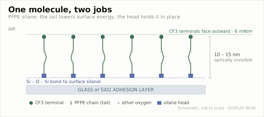
The material behind this behavior is mostly the PFPE silane family. PFPE stands for perfluoropolyether, a polymer in which every hydrogen on the carbon chain has been replaced by fluorine with oxygen inserted at regular intervals. Daikin labels its own product as modified PFPE dissolved in a fluorinated solvent.
Divide the molecule by function and there are two parts.
The tail is the fluorinated chain. Fluorine has high electronegativity and low polarizability, so the dispersion forces pulling on neighboring molecules are weak. When these chains line up facing outward they make the CF3 surface from the previous section, a face in the 6 mN/m range of critical surface tension. The oxygen inserted along the chain is there to give flexibility; a chain that bends well lies and stands evenly on the surface and builds a layer without gaps.
What matters here is not only that the chain exists but its orientation. If the fluorinated chain lies flat on the surface, what is exposed outward becomes the CF2 side and critical surface tension rises to 17. The terminal CF3 has to stand densely facing outward for the face to approach 6. That is why the same material can perform differently when deposition and curing go wrong.
The head is the silane group. This side bonds to the glass surface. Glass surfaces carry silanol groups, and once the silane group has hydrolyzed it condenses with them, producing an oxygen-mediated bond. With only a tail the molecule sits on the surface until it is wiped away; the head is what keeps it there. Humidity appears among the curing conditions in Section 4 because of this reaction.
The layer is thin. Manufacturer data puts it at the level of 10 to 15 nanometers and states that at that thickness it does not distort the optical properties of the glass. In practice the visible transmission spectrum nearly overlaps bare glass with little ripple across wavelength. It is not a layer that designs reflection the way an AR coating does; optically it is treated as absent. That contrasts with AG and AR, layers whose purpose is optical, which later episodes will take up.
The supply form is in the data as well. It is a liquid with 20 percent polymer dissolved in solvent, density 1.43 grams per cubic centimeter, appearance a pale yellow or clear liquid. Unopened shelf life is 1 year, storage between 5 and 25 degrees, away from direct sunlight.
Routes that avoid fluorine have been studied as well. Organosiloxane self-assembled monolayers aiming at AF behavior are the representative attempt. As the critical surface tension table shows, however, a hydrocarbon surface is 22 to 24 even as CH3 and overlaps the range of oil. The structural reason it is hard to place such surfaces alongside fluorinated materials on oleophobicity is that, even where hydrophobicity is reached. This is taken up again in Section 8.
4. How it is laid down
The same material can be laid down two ways. Manufacturer data states that both are supported.
Wet
Make a solution and apply it. Spray, dip, spin and flow coating are all used. The procedure the data sets out runs as follows.
Clean the substrate first. It specifies that plasma, UV and ozone, and chemical cleaning are generally effective. This step is not a formality, and the reason is the bonding structure from Section 3. If the silanol groups the head would bond to are covered in organics, no bond forms, and a molecule that failed to bond may contribute to the initial contact angle but disappears at the first rub.
Next is dilution. It is thinned with a fluorinated solvent such as a hydrofluoroether or perfluorohexane, and the starting point the data offers is 0.1 percent by weight of polymer, which is a 200-fold dilution. That means taking the 20 percent stock and thinning it 200 times. Spray quantity is given with a typical value of 30 to 60 grams per square meter.
The concentration goes this low because the target is close to a monolayer. Laying it on thicker does not improve performance. The number of sites available for bonding on the surface is fixed, and what piles up above them becomes a layer resting without bonds, which instead produces early wear.
Dry (PVD)
Vacuum deposition. The material is made into pellets and heated to vaporize inside PVD equipment. Here the data adds one condition, and this sentence connects straight to Section 7.
For best results, an SiO2 adhesion layer should be deposited on the substrate first, before Optool is applied.
The AF material bonds with silanol groups on a glass surface, so if the substrate is not glass or its surface condition is uneven, the sites to bond to are simply lacking. Laying an SiO2 layer first creates uniform bonding sites above it. In real cover windows AF often goes not on bare glass but on top of an optical multilayer such as AR, and in such stacks what the top layer is finished with governs the life of the AF. A separate patent covering exactly the configuration of AF over optical and scratch-resistant films exists for the same reason.
Curing
Both routes go through curing. The data offers two conditions.
| Condition | Temperature | Humidity | Time |
|---|---|---|---|
| Low temperature, high humidity | 60 degrees | 90 percent relative humidity | 1 hour |
| High temperature, ambient humidity | 150 degrees | ambient | 30 minutes |
And it states flatly that curing is required to form a chemical bond with the substrate. That humidity appears among the conditions stands out. For the silane to bond with the surface, hydrolysis has to happen first, and that reaction needs water. It reads as though a low temperature is compensated with humidity while raising the temperature lets ambient humidity carry it. It also says that managing curing as a matter of temperature alone can let results drift with the season.
After curing, unbonded residue is wiped or washed off with a fluorinated solvent. Molecules resting on the surface without bonds come off first, and initial performance turns erratic.
A process constraint is listed as well. This material decomposes and becomes hazardous when heated continuously above 200 degrees. That sets the temperature ceiling for whatever process follows the AF step. Cross that line while designing a thermal or bonding process downstream and what is lost is not only performance but safety.
Which route to take
The two are separated not by performance but by production conditions.
Wet, and spray in particular, is favorable on cost. The material needed to form a monolayer is small to begin with, and because the solution is sprayed from a sealed vessel, evaporative loss is also small. Against dip coating, the volume of solution required is smaller and the energy to drive off solvent is lower. It is also cited as able to lay a relatively uniform film on uneven or rough substrates.
Vacuum deposition is strong elsewhere. It has long been used where precise thickness control is required, as with optical components, and as noted it can lay the SiO2 adhesion layer first in the same flow. If AR multilayers are already being stacked in vacuum, carrying on to AF is natural.
Two burdens come with it. One is curvature. If the substrate is bent, deposition rate varies by location, so masking is needed to shield the fast regions and match the slow ones. Masking complicates chamber tooling and lowers the overall deposition rate. This burden grew as cover windows moved from flat to 2.5D and 3D curves.
The other is large area. As area grows, the required vacuum level and pump-down time grow with it. Beyond phone cover glass, at automotive covers or notebook panels, this constraint binds first.
Handling and storage
The data also shows the material to be moisture sensitive. Storage is specified between 5 and 25 degrees away from direct sunlight, and after use the instruction is to close the cap to prevent evaporation and moisture exposure, and to minimize the air in the bottle before resealing or replace it with a dry inert gas such as nitrogen or argon.
This instruction follows from the bonding chemistry of Section 3. Silane groups hydrolyze on contact with water. That reaction is only useful when it happens at the surface; if it happens inside the bottle first, the molecules condense with each other. The unopened shelf life of 1 year comes from the same place. Adding humidity in the curing condition and removing it in the storage condition is the basis of handling this material.
5. What it is measured with
The specification of this layer is not optical. It is made of surface properties and touch.
Contact angle and hysteresis
Contact angle is measured with two liquids, water and n-hexadecane. In practice, though, contact angle is not a single value. The advancing angle measured while growing the droplet differs from the receding angle measured while shrinking it, and the gap is called contact angle hysteresis.
Instrument makers’ literature gives two reasons this matters. First, hysteresis on the order of tens of degrees signals chemical non-uniformity or roughness-related non-uniformity in the coating. Second, wiping performance correlates with hysteresis, and the smaller the hysteresis the better it wipes.
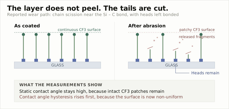
And there is one more point on this layer, the most practical of all. As an AF coating degrades it is reported that the static contact angle holds high while hysteresis rises first. Watch only the static contact angle and the number looks fine while the coating is already going bad. The problems of Sections 6 and 7 announce themselves here.
Sliding angle and friction coefficient
Sliding angle is the tilt at which a droplet begins to roll. If contact angle is a static value, this one is dynamic, and it maps directly onto wiping in real use.
Kinetic friction coefficient corresponds to the feel of a finger sliding across. The measurement conditions the manufacturer discloses are specific. Labthink FPT-1 equipment, 200 gram load, 200 millimeters per minute, paper friction pad. Setting friction curves side by side, what the same data points at is not only magnitude. On bare glass the curve chatters like saw teeth; on the coated face it is smooth. Stick-slip, sliding and catching in turn, is reduced, and that is the smoothness a finger feels crossing the screen.
Worth marking here. Finger feel is managed as a specification item. A domain easily waved away as perceived quality has come down, on this layer, to a number called friction coefficient. As will be seen later, this value splits by more than two times even between materials in the same family.
How the fingerprint itself is reproduced
Contact angle and friction coefficient are measured with surrogate liquids. The final performance, whether a fingerprint wipes off, has to be measured with a fingerprint, and human fingers are not reproducible. So artificial fingerprints are made.
The method set out in patents and papers runs like this. An artificial secretion of defined composition is prepared and transferred to the surface by stamping with a silicone stamp at a defined force. A heated solution blending glyceryl trioleate with artificial sebum is described. Removability is evaluated by wiping with a cloth of defined mass at defined force and speed. Where quantification is needed, a known amount of sebum is deposited with a spraying device and the actual deposited mass is verified with UV-visible spectroscopy and microgravimetry.
That is the measurement system of this layer. Three tiers, put simply. Contact angle and hysteresis measure the property of the material; sliding angle and friction coefficient measure the feel in use; and the artificial fingerprint test measures the final performance. That the three do not always point the same way is the story of the next section.
6. How long it lasts, and how to read that number
The life of an AF layer is measured by abrasion testing. The widely used method rubs the surface with steel wool and counts the reciprocations until contact angle falls below a set level.
The conditions Daikin’s European technical data gives are these.
Maximum number of reciprocations while the water contact angle stays at or above 100 degrees. Steel wool #0000, load 1 kilogram per square centimeter, stroke 6 centimeters, speed 60 per minute.
The same data places two of its own products side by side, and that table is the core of this episode.
| Item | Optool UD509 | Optool DSX |
|---|---|---|
| Water contact angle | 116 degrees | (not listed in the table) |
| Water sliding angle | 6 degrees | 8 degrees |
| Steel wool abrasion | 24,000 cycles | 6,000 cycles |
| Kinetic friction coefficient | 0.03 | 0.07 |
The water contact angle in the DSX data issued by the US affiliate was 109 degrees. UD509 in the European data is 116 degrees. A difference of 7 degrees. Yet in the same table the abrasion counts open up four times, at 24,000 and 6,000. The friction coefficient differs by more than two times as well, at 0.03 and 0.07.
Here is the conclusion running through this episode. An AF coating cannot be chosen by contact angle. The initial contact angle says how well this layer works at the start and says almost nothing about how long it goes on working. In real use it is the latter that matters. Nobody complains that fingerprints will not wipe off a new phone.
The hysteresis from Section 5 layers onto this. The static contact angle responds late as degradation proceeds, and hysteresis rises first. Manage the state of this layer by static contact angle alone and you are wrong when choosing a product and late when tracking degradation.
The same data shows the trap in handling numbers. The US affiliate’s DSX sheet lists steel wool abrasion at 4,000 cycles with no test conditions alongside. In the European comparison table the same product is 6,000. Rather than one being wrong, they are better read as values from tests under different conditions. Change the load, stroke, speed and above all the contact angle at which the test is called finished, and the count moves however you like. Drop the criterion from 100 degrees to 90 and the count for the same sample rises a great deal.
So the rule for reading data on this layer is one line. An abrasion count with no conditions attached cannot be used for comparison. If you are handed a sheet setting two companies’ products side by side on counts alone, that table is not evidence but marketing. Check first whether the conditions on both sides are the same.
The caveat the manufacturer attaches itself is carried over here as well. The property values above are representative, not guaranteed, and are stated as unsuitable for use as specifications.
7. Why it wears out
To see why lifetimes split like this, look at where the wear actually happens.
The intuitive picture is that the coating rubs off. A thin film is worn away bit by bit and where it is gone, fingerprints start to stay. But this layer is about 10 nanometers thick and is closer to a structure of single molecules bonded standing on glass. “Rubbing off” does not fit cleanly.
Studies of degradation in this family of coatings point somewhere else. Rather than the silane head coming away from the glass, the fluorinated chain side breaks. In particular the Si-C bond linking the PFPE chain to the silane group is identified as the weakest link in the chain. Analyzing surfaces before and after abrasion with XPS to track silicon and fluorine content is the method used in such work.
If that account holds, the picture inverts. An abraded surface is left with the head still there and only the tail cut away. The number of molecules attached to the surface has not dropped much, but the fluorinated chains facing outward have shortened or gone, so only the function of lowering surface energy is lost.
Hold the critical surface tension table from Section 3 against this and the path of degradation appears. An intact layer has CF3 facing outward, making a face in the 6 mN/m range. When chains break, CF2 is exposed in their place or the silane-side structure is revealed, and the effective surface energy rises. A partially broken surface becomes an uneven face mixing CF3 regions with regions that are not, and as Section 5 showed, the signature of such a face is exactly rising hysteresis. The static contact angle still reads high thanks to the CF3 regions that remain, but the droplet catches when it moves.
The numbers of the previous section are explained here. The initial contact angle measures how well the tails are lined up; the abrasion count measures how long those tails stay attached. They measure different things, so it is only natural that they do not move together. The gap between 116 and 109 degrees is a difference in tail arrangement, but the gap between 24,000 and 6,000 comes from chain structure, degree of crosslinking, and the density of the sites holding on.
The SiO2 adhesion layer recommendation from Section 4 runs along the same line. Make bonding sites dense and uniform and the same material lasts longer. Reports that samples with an alumina or silica adhesion layer held their contact angle longer in abrasion testing do not run against this direction. And it explains why the cleaning conditions of Section 3 and the curing conditions of Section 4 are written out so specifically. The life of this layer is largely decided not at the moment the material is chosen but in the process that attaches it.
That said, the mechanism described in this section rests on academic literature and has not been confirmed against primary data with conditions and numbers stated, the way a manufacturer technical data sheet does. The account that the Si-C bond is the weakest link, and that chain scission is the main path, should be read as the direction studies point to and is hard to use as grounds for asserting the actual degradation path of a specific product.
Rubbing is not the only path to wear
The steel wool test looks only at mechanical abrasion. In real use the paths that break this layer down are several, and the literature names at least four together.
First, mechanical abrasion. The chain scission path seen so far. Fingers, clothing and grit in a pocket belong here.
Second, hydrolysis. Hydrophobic coatings are noted as tending to fail by hydrolysis after exposure to harsh solvent conditions. The bond linking surface and coating is an oxygen-mediated structure, so that bond itself can react with water and run backward. The storage instructions of Section 4 are the other face of this property.
Third, ultraviolet light. Long exposure to sunlight can bring yellowing or degradation, so UV stability is separately required for outdoor use. It is an item that binds in automotive displays before phones. A display above a dashboard takes high temperature and strong ultraviolet at the same time in summer.
Fourth, adhesion failure. Fluorinated compounds are noted as adhering poorly to glass substrates, which can lead to delamination under mechanical stress or thermal cycling. This is a different failure from chain scission. It is closer to the whole layer coming away, which is why the SiO2 adhesion layer and the cleaning conditions of Section 4 matter.
Resistance to cleaning agents reads differently across sources. On one side there is the general statement that environments exposed to detergents, solvents and industrial atmospheres require a chemically inert coating; on the other there is a report that rubbing with isopropyl alcohol left the water and methylene iodide contact angles unaffected. It is best read as varying with composition, and in fact a patent states that including a compound with a silazane group improves alcohol resistance.
Put the four together and the conclusion of Section 6 is confirmed once more. A steel wool count measures one of the four paths. A high number is no guarantee of surviving 3 years in an automotive environment. Which is why the literature on the durability of this layer converges on one diagnosis. Most AF coatings have excellent initial performance and degrade quickly under real use conditions. Durability is the bottleneck to commercialization.
8. What is riding on this layer now
Supply structure
A small number of chemical companies make this material. Names cited together as suppliers of commercial display AF coatings include Daikin, Shin-Etsu Chemical, AGC Chemicals, 3M, Solvay, PPG, Schott, Dow and SDC Technologies. Among them Daikin’s Optool family has published technical data, which is why the numbers in this episode could be drawn from it. Values from the other companies are not published in a form comparable under the same conditions. That is where the rule of Section 6 binds directly in procurement practice.
In Korea, cover glass maker JNTC announced in 2024-02 that it had independently developed prior technology for AF coating. The announcement states that abrasion resistance improved more than 20 times against a global customer’s criterion, and that where the AF effect of existing products lasts several months, theirs holds 5 to 6 years or more. This is a company announcement with no disclosed comparison target or test conditions, so by the principle set out above it should be handled as a number with no conditions attached.
Regulation
What is riding most heavily on this layer right now is not performance but regulation.
The universal PFAS restriction under discussion in the European REACH framework centers on prohibiting non-essential PFAS in articles above 0.1 percent by weight, with the scope of covered substances cited at over 10,000. The European Chemicals Agency began final consultation on the proposed restriction on 2026-03-26, and the final opinion of the Committee for Socio-Economic Analysis is expected at the end of 2026.
The common rebuttal is that polymers are exempt. What analyses of this discussion point out in common, though, is that it is not enough for a supplier sheet to say polymer exemption. Low molecular weight fractions, or fragments that can come away during use, may fall within scope.
Lay the mechanism of Section 7 over this and the problem becomes clear. If the degradation of this layer proceeds by chains breaking, then where the broken fragments go becomes a regulatory question. What makes the performance is the fluorinated chain, and what comes away as it wears is also the fluorinated chain.
This is where the non-fluorinated approach mentioned in Section 3 returns. Research aims at low surface energy without fluorine, as with organosiloxane self-assembled monolayers, but as the critical surface tension table shows, a hydrocarbon surface is 22 to 24 even as CH3 and overlaps the range of oil. There are several routes to repelling water, but fluorine was overwhelming at repelling oil, which is the fact seen in Section 2, and it is what makes the regulatory response hard.
What remains
This layer is 10 nanometers thick and, counted as cost, is not a large share of the cover window process. Yet it is the only layer a user touches every time they touch the screen, and when it wears the user knows at once. And the foundation of its material now sits in the middle of a regulatory debate.
Reduced to three lines, what this episode marked out is this. AF does not stop fingerprints, it stops them spreading. What does that work is CF3 standing outward, and wear begins where those chains break. And so the initial contact angle does not represent the performance of this layer.
The next episode takes up a different layer on the same face. A layer where the problem is not fingerprints but light, AG. It works by roughening the surface on purpose to scatter reflection, and it runs head-on into the demand seen in this episode that the surface be smooth and uniform. That is where the demands on one face begin to collide.